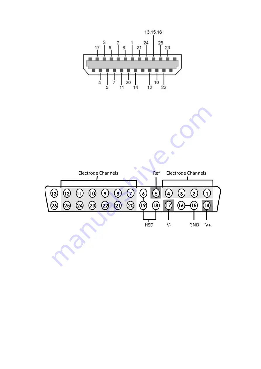
Diagram re
fl
ects pin numbers (not channel numbers).
For information on making custom connections to the commutator, see
ACO32 and ACO64 Ampli
fi
er Connector Pinout
Connectors are labeled A and B on ACO32 and A, B, C, D on ACO64. Electrode channels below
are relative to the electrode/headstage connected to the corresponding interface receptacle.
ACO32/ACO64 Motorized Commutators | 20


