AN-000368
Document Number: AN-000368
Page 5 of 11
Revision: 1.0
3
QUICK SETUP
3.1.
USING MOTIONLINK SOFTWARE
1.
Download and install MotionLink software.
2.
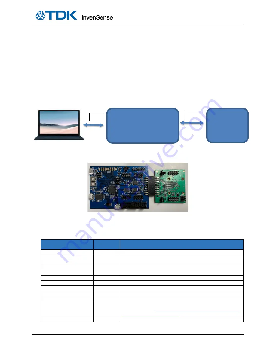
Connect the FTDI USB (CN6) to PC and open MotionLink for quick testing, as shown in the block diagram
3.
Click on Start MotionLink to get to the GUI window.
4.
Refresh COM and if needed, connect EDBG USB (J500) to PC and Flash MCU Firmware.
5.
Click on Select and Configure Sensor Board and find the correct part number.
6.
Connect to the serial port and power on the board.
For further help, click on the Help button on the top bar for the MotionLink user manual or troubleshooting help.
Figure 2. Block diagram
Figure 3. DK-UNIVERSAL-I connected to EVB
3.2.
CONNECTORS
Table 1 details the TDK SmartMotion Platform Ver. I connector and header reference names and descriptions.
CONNECTOR NAME
CONNECTOR
REF #
CONNECTOR FUNCTION DESCRIPTIONS
TDK Sensor EVB Connector
CN1
External TDK sensor EVB connector
Other Sensor DB
CN2/CN3
Daughter board connector for Mag sensor. I
2
C interface only
TDK Sensor DB
CN4/CN5
Daughter board connector for TDK sensor. I
2
C and SPI interfaces
FTDI USB
CN6
USB connector for FTDI USB to serial UART interface
JTAG Connector for SAMG55
CN7/CN8
JTAG Connector for SAMG55 debugging
EDBG LEDs
D500/D501 EDBG LEDs. D500 is green and D501 is yellow
Sensor I
2
C Selection
J1
Select host I
2
C connections, for IMU sensor and other sensors
PWR Source Select
J2
Board power source selection
VDDIO Voltage Select
J3
Selects voltage level between 3.3V, 1.8V, 1.2V for VDDIO
Test pins
J4
Digital signal test pins
Extension 1
J200
Extension header 1. Has same function as J200 on Microchip’s Xplained-
Pro board. Refer to
http://www.atmel.com/Images/Atmel-42389-SAM-
G55-Xplained-Pro_User-Guide.pdf
for more details
SAMG55 USB
J301
MCU SAM G55 USB connector
TDK Sensor (EVB)
SPI Slave
Or
I
2
C Slave
DK-UNIVERSAL-I Board
CN1
CN6


