TDK-Lambda PHV Series Скачать руководство пользователя страница 2


   83-000-020   Rev B 

THREE YEAR WARRANTY 

TDK-Lambda  Americas,  Inc.  (405  Essex  Road,  Neptune,  N.J.  07753),  warrants  that  the  unit  is  free  from  defects  in 
material or workmanship for a period of THREE YEARS from the date of initial shipment. TDK-Lambda Americas Inc. 
will  service  and,  at  its  option,  repair  or  replace  parts  which  prove  to  be  defective.  This  will  be  done  free  of  charge 
during  the  stated  warranty  period. This  warranty  excludes  defects  resulting  from misuse, unauthorized  modification, 
operation  outside  the  environmental  or  safety  specifications  of  the  power  supply,  or  improper  site  preparation  or 
maintenance. The customer shall contact  TDK-Lambda Americas Inc., for warranty service or repair as described in 
the RETURNING EQUIPMENT section. The customer shall prepay shipping charges. If the unit is covered under the 
foregoing warranty, then TDK-Lambda Americas Inc. shall pay the return shipping charges. 

The “WARRANTY”, “CLAIM FOR DAMAGE IN SHIPMENT”, and “RETURNING EQUIPMENT” information applies to 
equipment  purchased  directly  from  TDK-Lambda  Americas  Inc.  End  users  receiving  equipment  from  a  third  party 
should consult the appropriate service organization for assistance with these issues. 


THIS LIMITED WARRANTY IS IN LIEU OF,  AND  TDK-LAMBDA  AMERICAS INC. DISCLAIMS  AND EXCLUDES, 
ALL  OTHER  WARRANTIES,  STATUTORY,  EXPRESS  OR  IMPLIED,  INCLUDING,  WITHOUT  LIMITATION,  ANY 
WARRANTY OF MERCHANTABILITY OR FITNESS FOR A PARTICULAR PURPOSE, OR OF CONFORMITY TO 
MODELS OR SAMPLES. 


CERTIFICATION 

All test and measuring equipment used by TDK-Lambda Americas Inc. for Final Acceptance Testing are traceable to 
primary standards certified by the National Institute of Standards and Technology. 


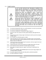
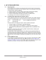
LETHAL VOLTAGES PRESENT!


All  power  supplies  contain  hazardous  voltage  and  energy.  The  power  supply  must  only  be  operated  by  qualified 
personnel who have read this operator’s manual and are familiar with the operation, hazards and application of the 
power supply. Proper care and judgment must always be observed. 

1. 

Before  connecting  input  AC  power,  ensure  all  covers  are  in  place  and  securely  fastened.  Ensure  the  required 
safety ground to chassis is installed and sufficient cooling is supplied. 

2. 

Proper  grounding  from  the  input  AC  power  is  required  to  reduce  the  risk  of  electric  shock,  and  to  comply  with 
safety agency and code requirements. 

3. 

Use extreme caution when connecting input AC power. Only apply the input voltage specified on the rating label. 

4. 

Use extreme caution when connecting any high voltage cables. Never handle any output cables when the power 
supply is operating. 

5. 

After a power supply is switched OFF, its output section will retain a charge which may be lethal. Allow sufficient 
time  for  self-discharge  before  handling  anything  connected  to  the  output.  The  discharge  time  specified  in  the 
Safety Notes does 

NOT


include extra time required to discharge the energy stored in the user’s load. 

6. 

When user serviceable fuses are present, always replace fuses with the same type and Volt/Amp rating. 

7. 

Never attempt to operate the power supply in any manner not described in this manual. 

8. 

Never  remove  DANGER  or  WARNING  labels  from  the  power  supply.  Replace  lost  or  damaged  labels 
immediately. Contact TDK-Lambda Americas Customer Service for replacement labels. 

9. 

The  power  supply  may  be  serviced  only  by  TDK-Lambda  Americas  Inc.  factory  qualified  service  personnel. 
Breaking  the  warranty  seal  will  void  the  warranty.  Prior  to  opening  the  power  supply,  contact  TDK-Lambda 
Americas Inc. Customer Service for a written Service Waiver and a replacement warranty seal. 

Содержание PHV Series

Страница 1: ...OPERATOR MANUAL FOR PHV Series High Voltage POWER SUPPLY Document 83550001 Rev C TDK LAMBDA AMERICAS 405 Essex Road Neptune NJ 07753 Tel 732 922 9300 Fax 732 922 9334 Web www us tdk lambda com hp...

Страница 2: ...ETHAL VOLTAGES PRESENT All power supplies contain hazardous voltage and energy The power supply must only be operated by qualified personnel who have read this operator s manual and are familiar with...

Страница 3: ...ive 93 68 EEC European Community Conformity Assessment Product Mark IEC 348 Attention consult Accompanying documents IEC 60417 1 5036 Dangerous voltage IEC 60417 1 5019 Protective earth e g power line...

Страница 4: ...necting the High Voltage Output 14 4 6 1 HV Output Polarity 14 4 6 2 Floating Output 14 4 6 3 HV Output Connector 14 5 CONTROLS INDICATORS CONNECTORS 16 5 1 Front Panel Layout 16 5 1 1 Overtemp LED Re...

Страница 5: ...sired output voltage current levels 24 6 6 Turning ON the output 24 6 7 CC CV Mode Indication 25 6 8 Turning the unit OFF 25 7 ANALOG REMOTE CONTROL OPERATION 26 7 1 The Non Isolated Analog Interface...

Страница 6: ...HV Half Rack Rear Panel with Reversible Output 21 List of Tables Table 1 PHV Model Description Format 7 Table 2 PHV HV Output Connector Types 15 Table 3 Front Panel Controls and Indicator Functions in...

Страница 7: ...N ARE CONTAINED IN ADDENDA AND TAKE PRECEDENCE IF CONFLICTS EXIST PLEASE TAKE CARE TO REFER TO THE CORRECT INFORMATION FOR YOUR UNIT 1 2 Introduction TDK Lambda PHV series are state of the art precisi...

Страница 8: ...or Correction reduces RMS current draw 1 3 2 Benefits Lightweight switchmode design Benchtop chassis configuration with optional rack mount kit Low output stored energy provides greater safety Immunit...

Страница 9: ...n in a clean dry environment 1 5 2 This product is designed for pollution degree 1 1 5 3 This product is designed for Transient Overvoltage Category II 1 5 4 Ensure all covers are in place and securel...

Страница 10: ...upply family For additional options the customer may contact the Sales Department at TDK Lambda Americas Special options are typically shown as a four digit suffix to the model number PHV 20 N 15 USB...

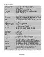
Страница 11: ...8 83550001 Revision C 2 SPECIFICATION...

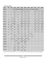
Страница 12: ...9 83550001 Revision C Mechanical Details...

Страница 13: ...ed Service Center should be contacted if The power supply is mechanically or electrically damaged The power supply requires on site calibration or replacement warning decals The customer has questions...

Страница 14: ...11 83550001 Revision C This Page Left Intentionally Blank...

Страница 15: ...may require addition of a system heat exchanger Do not operate bench top units without the feet installed Do not expose the unit directly to sunlight to avoid unwanted thermal effects 4 3 Orientation...

Страница 16: ...e switch or circuit breaker must be located close to the power supply and within easy access of the operator The switch or circuit breaker must be marked as a disconnecting device for the equipment If...

Страница 17: ...this connection should not be removed If required the Ground link can be removed and the HV return must be connected to Ground at the load In the event of load arcs or flashovers the return connector...

Страница 18: ...nstalled on one end PHV100PXX S1100 2 DS 2124 4 9ft cable with connector installed on one end PHV150PXX S1155 2 DS 2121 4 9ft cable with connector installed on one end PHV200PXX PHV300PXX Call factory...

Страница 19: ...ode switch 1 and power on switch The PHV can be operated locally from the front panel or remotely 1 via an optional remote interface located on the rear panel Typical front panel layout of the PHV pow...

Страница 20: ...utput is turned ON 5 1 13 14 HV ON OFF Button Turns HV Output ON OFF does not disconnect the HV output or AC Input 5 1 14 15 NEG Polarity LED 1 If optional polarity reversal is installed Illuminates t...

Страница 21: ...approximately 0 1 to 100 of rated This control will only operate in local mode if the supply is operated in remote mode the local voltage set control has no effect 5 1 6 OVP Indicator LED Ref 6 Indica...

Страница 22: ...lly hazardous voltage may be present 5 1 14 HV ON OFF Button Ref 14 DO NOT DEPRESS THE HV ON PUSH BUTTON UNLESS A SUITABLE LOAD IS CONNECTED TO THE POWER SUPPLY S OUTPUT CABLE AND THE LOAD IS CORRECTL...

Страница 23: ...both remote analog and digital interfaces is operating in remote control mode via the Digital interface 5 1 23 Busy LED Ref 23 Indicates presence of traffic on the optional Digital interface 5 2 Rear...

Страница 24: ...ce connector 5 2 3 4 Remote Interface 15pin sub D type receptacle for remote analog control interface 5 2 4 5 GND stud M4 for 1 AC inputs M6 for 3 AC inputs 5 2 5 6 Fuse AC power fuse 5 2 6 7 AC Input...

Страница 25: ...al Interface Ref 3 Location of optional Digital control interface Options are USB IEEE 488 LAN Ethernet RS232 RS422 RS485 Profibus 5 2 4 Remote Analog Connector Ref 4 A 15 pin D sub female connector t...

Страница 26: ...23 83550001 Revision C This Page Left Intentionally Blank...

Страница 27: ...the limit voltage is displayed on the VOLTAGE meter To operate with no output voltage limit turn the V LIMIT potentiometer fully clockwise The V LIMIT LED will extinguish Once the OVP limit has been s...

Страница 28: ...gure 1 The ON LED will extinguish Item 12 in Figure 1 to show the HV output is OFF Wait until the output voltage has reached a safe potential then turn off the POWER switch Item 11 in Figure 1 This pr...

Страница 29: ...rface INA option features up to 2kV isolation from chassis ground 7 1 The Non Isolated Analog Interface ANA option Note that analog and digital ground pins 6 and 9 for the external programming signals...

Страница 30: ...els set by 0 10V signals and HV ON OFF function by switches or relay contacts Some examples for operating the unit in various combinations of LOCAL and REMOTE modes are shown in sections 7 1 2 through...

Страница 31: ...ies resistance is 11k 4 N C Not connected 5 N C Not connected 6 Digital Ground Ground for digital circuits Isolated from chassis to 2 000V 7 POL SET I Polarity set signal for units equipped with optio...

Страница 32: ...29 83550001 Revision C This Page Left Intentionally Blank...

Страница 33: ...rface supports up to 2000 programming commands per second To operate the unit in Remote Digital mode set the LOCAL REMOTE switch see Item 18 in Figure 2 to the REMOTE position the LOCAL LED will extin...

Страница 34: ...31 83550001 Revision C This Page Left Intentionally Blank...

Страница 35: ...channel and Master Pin 5 to Slave Pin 15 for the Current channel Hard wire Slave Pin 12 to Slave Pin 6 to turn on the HV output The HV output cables must be connected together at the load 9 2 Paralle...

Страница 36: ...33 83550001 Revision C This Page Left Intentionally Blank...

Страница 37: ...34 83550001 Revision C Notes...

Страница 38: ...plication issues or questions that are not covered in this manual please do not hesitate to contact the factory and our team of experienced HV application engineers Contact the Factory We are here to...

Отзывы: