


2800 Laura Ln, Middleton WI 53562 | 800.288.9383 Fax: 608.836.9044 | www.tcsbasys.com
15
USER
INTERFACE
c.
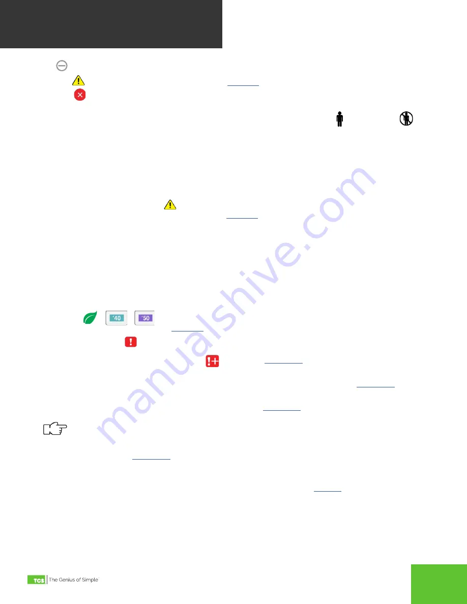
Idle
: Neither heating nor cooling is active.
d. Warning
: Heating or cooling lockout in effect. See
for more information on this feature.
e. Disabled
: The control is currently disabled and not heating or cooling. This is typically shown on startup during
the power on delay, or when fan proving has failed.
4. Occupancy State: This button indicates the current occupancy state as being occupied or unoccupied
.
Touching this button overrides the occupancy state (switches between occupied/unoccupied) for three hours, or until
a schedule change. The time when the override will expire is shown on the button. Touching and holding the occupan-
cy state button until the border changes (about 5 seconds), causes the override to hold until the next change in sched
-
ule. Whenever the occupancy state is overridden, touching the Occupancy State button again cancels the override.
The following BACnet objects configure the use of this button:
• Occupancy Override Mode: MSV-701
•
Occupancy State Override Time: PIV-703
5.
DI Setpoint Setback Active Indicator
: This symbol is visible when DI Setpoint Setback is active. Touching this
symbol displays a brief explanation of the feature. See
for an explanation of this feature.
6.
Info Text: This two line text field may be written from the network, and can be useful for showing additional informa
-
tion such as the current weather. If not being written from the network, the outdoor air temperature is visible whenever
a sensor is physically connected, or when the thermostat is receiving a valid outdoor temperature reading. Info text
can be customized via CSV-506.
7. Display Banner: The display banner contains the current date and time, and may contain the device name. The device
name is typically used describe what area or unit the thermostat is controlling. The device name can only be changed
using Ubiquity Cloud or an external BACnet configuration tool . The time can be set to display in a 12 hour or 24 hour
format using the Date/Time screen in the Advanced Settings menu. The contents of the banner can be customized
using MSV-505.
8.
Economizer
:
This symbol is visible when the Economizer is active. Touching this symbol provides
a brief explanation of this feature. See
for an explanation of this feature.
9.
Service Status Indicator
: This symbol is visible only when one or more service status is active. Touching this
symbol navigates to the service status screen where any active service status is viewable. When there are more than
one service status active, a plus sign next to the
for more information on service status.
10.
Settings: Touching this button navigates to the Settings menu. If an access code has been set, the user will be
prompted to enter the code before they are permitted to proceed to the Settings screens. See
information on Setting screens. All programming is done on these screens.
11. Status: Touching this button navigates to the Status screens. See
for more information on the Status
screens.
Touching and holding the Status button for 5 seconds brings up a dialog asking the user if they would like to
force a device restart. If confirmed, the UbiquiSTAT immediately restarts.
12. About: Touching this button navigates to the About screen. This screen shows product information, such as version-
ing and serial number. See
for more information about the About screen.
4.2 Status Screens
Touching the Status button on the home screen will bring up the Status screens (see
). These screens display real
time information about the state of the control as well as inputs and outputs. This information is grouped into three sub
screens: system, advanced, and network.


