Unit Circuit Analysis and Testing
----Backlight and Dimming
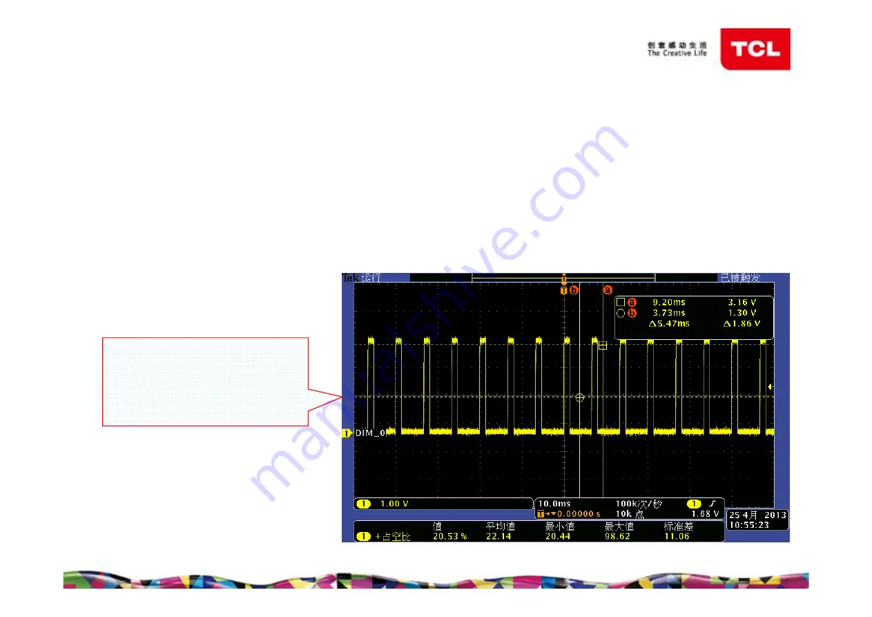
Dimming waveform when
“Backlight” is set to 0
in setting menu.
(“Nature Light” off)
-32-
①
Pin J4 of U400 sends out a high or low level, across R003, then
directly send to power board through pin12 of P001 on the main board,
control the backlight on or off.
②
Pin B8 of U400 sends out PWM signal, across R006, then directly
sends to power board through pin11 of P001 on the main board, adjust
back light brightness.
Содержание MS901K-AP Series
Страница 1: ...Training Material of MS901K AP Chassis...
Страница 4: ...MS901K AP Series Menu Display 2 Homepage 1 Homepage 2 All Apps 3D Games...
Страница 5: ...MS901K AP Series Menu Display 3 Menu Picture Setting Source Settings...
Страница 14: ...12 07 240WU5 MS3G external antenna External Antenna To P1005 Module Introduction 2 4G Module for 85...
Страница 15: ...Chassis Block Diagram MS901 13 DDR3 1V5 DDR2 1V8 DDR1 2V5...
Страница 16: ...Chassis Block Diagram 6M40 14...
Страница 17: ...Power Supply Block Diagram 15...
Страница 18: ...Power Supply Block Diagram 16...
Страница 25: ...Key Test Point DC to DC 24V to 12V 23 L007 U004...
Страница 26: ...Key Test Point DC to DC 24 24V to 5V L001 Q004 U005...
Страница 27: ...Key Test Point DC to DC 25 24V to 6M40_5V L1103 U1105...
Страница 28: ...Key Test Point DC to DC 26 5V to 1V5_DDR U001 same with 6M40_5V to 1 5V_DDR_S U1102 L016 L1102 U001 U1102...
Страница 31: ...Key Test Point 29 U101 5V to TU_3V3 LDO...
Страница 32: ...Key Test Point 30 Q1401 Panel Power Q1402...
Страница 35: ...Unit Circuit Analysis and Testing Backlight 100 Backlight 50 33 Backlight and Dimming...
Страница 47: ...Trouble Shooting No Picture 45...
Страница 48: ...Trouble Shooting No Sound 46...
Страница 49: ...Trouble Shooting Abnormal Picture 47...
Страница 50: ...Trouble Shooting Network Fault wired 48...
Страница 51: ...Trouble Shooting Network Fault wireless 49...
Страница 59: ...Thank you...


