background image

TCI Library  www.telephonecollectors.info 

Содержание ITT

Страница 1: ...BASIC INSTALLATION AND KEY TELEPHONE SYSTEM MANUAL Performance Development Center ITT TCI Library www telephonecollectors info...

Страница 2: ...nate errors the company disclaims liability for difficulties arising from interpretation of the information contained herein Any comments or suggestions for improving this manual would be appreciated...

Страница 3: ...TCI Library www telephonecollectors info...

Страница 4: ...11 K 2510 DESK TELEPHONE 12 K 2554 WALL TELEPHONE 13 K 2564 K 2565 KEY TELEPHONES 14 TEN AND TWENTY BUTTON KEY TELEPHONES 15 ISS 2 PDC AB 001 CONTENTS SECTION RINGERS 16 REMOTE SIGNAL DEVICES 17 DIALS...

Страница 5: ...TCI Library www telephonecollectors info...

Страница 6: ...rious types of ITT station instruments replace ment parts and auxiliary devices and MDF and IOF organization and arrangement 1 02 The information in this manual is general in nature and relates pri ma...

Страница 7: ...TCI Library www telephonecollectors info...

Страница 8: ...utomatic impact con necting tool is shown in figure 2 00 This tool is used to make wire ter minations on type 66 connecting blocks and similar quick connect terminal blocks The tool comes equipped wit...

Страница 9: ...the blade to expose the op posite end then retighten the screw See figure 2 02 Place the wire in the fanning strip and loop it over the hook in the termin I c Place the connecting tool on the terminal...

Страница 10: ...ISS 2 PDC AB 001 BLADE IN TERMINATE ANO CUT POSITION BLADE IN TERMINATE ONLY POSITION FIGURE 2 02 Changing The Cutting Blade FIGURE 2 03 Push Drill 2 3 TCI Library www telephonecollectors info...

Страница 11: ...ries with the line cords The capacitor prevents a short circu it in the test set from interfering with a call in progress and allows monitoring of a line before any tests are made 2 07 The hand test t...

Страница 12: ...was removed While listening to the test receiver momentarily touch the other test clip to the loose wire If a click is heard a short circuit is in dicated d Open circuit test To test for an open circ...

Страница 13: ...the red test clip The LED on the test set lights when the red clip is con nected to the ring lead d NOTES 1 Test c will only work when 48 volt battery is on the line 2 If no ground is available con ne...

Страница 14: ...cable It uses 1 2 inch wide staples 5 8 or 7 8 inches long I DISTANCE WIRE 1 STAPLER LENGTH NOTE When fastening station wire or cable staples should be placed the length of the stapler about 7 inches...

Страница 15: ...TCI Library www telephonecollectors info...

Страница 16: ...rs to the cable which extends from a wall outlet connecting block etc to a multi 1ine telephone set d Station wire The term station wire refers to the wire which ex tends from a wall outlet con nectin...

Страница 17: ...0 Y 3 2 iii TABLE 3 03 Inside Wire Cable Cont TYPE CIRCUIT TIP RING BINDER NO 18 Y GN GN Y 19 Y BN BN Y 20 Y SL SL Y 21 V BL BL V BL W 22 V 0 0 V 23 V GN GN V 24 V BN BN V 25 V SL SL V 50 Pair 26 50 R...

Страница 18: ...et Table 3 06 lists stock numbers for such cables and shows the cable symbol ISS 2 PDC AB 001 TABLE 3 06 25 Pair Cables With Two Female Connectors SYMBOL CODE STOCK NO A25 A50 31262 A25 A100 31263 A25...

Страница 19: ...14 3 4 3 06 50 pair cables a A cable with two female con nectors on one end is identified by a number such as A50 x 25 where A indicates a female connector 50 denotes the number of pairs and 25 indica...

Страница 20: ...K NO A75 x 25 31044 A75 x 50 31045 A75 x 75 31046 A75 x 100 31047 A75 x 150 31049 A75 x 200 31051 ISS 2 PDC AB 001 3 08 100 pair cables A cable with 5 female connectors at one end is identified by a n...

Страница 21: ...TCI Library www telephonecollectors info...

Страница 22: ...e provided in the follow ing paragraphs a Place the AMP insertion tool on a flat surface with the color bar guide assemblies facing toward you Open the handles so that they are parallel to the table s...

Страница 23: ...group should be on the bottom When the cable is in place secure the cable clamp Rotate the leh and right color bar guides to agree with the type of connector male or female to be attached to the cable...

Страница 24: ...CODE LH RH Vio Tracer V10 Body Yel Tracer Yel Body Blk Tracer Blk Body Red Tracer Red Bcdy WhtTracer Wht Body ISS 2 PDC AB 001 CABLE CLAMP GP GP 4 TRACER COLOR POSITION FOR MALE CONNECTOR VEL BLK POS...

Страница 25: ...efer to figure 4 03 for the proper color code sequence Repeat step g for each color group of wires BLOCK HOLDER SECURREO i j k I Make a final check to see that all wires are properly seated in the gui...

Страница 26: ...llow the wire holders to fall away Release the cable clamp and slide the con nector upward out of the block o Inspect the connector to see that each wire is properly terminated then slip the cover ove...

Страница 27: ...TCI Library www telephonecollectors info...

Страница 28: ...ock meas ures approximately 2 7 8 inches wide and 13 3 8 inches long It consists of 50 horizontal rows of terminals with each row split into two groups of 3 terminals The terminals are arranged to for...

Страница 29: ...re 5 01 The block is for use in connecting a multi line desk or wall mounted telephone equipped with a plug ended line cord The basic block consists of a 50 pin female connector wired internally to 50...

Страница 30: ...RE 5 02 Type 42A Connecting Block Standoff H3B5 HO 5 06 The H385 HO standoff shown in figure 5 03 is used to mount type 668 connecting blocks Three standoffs are required to mount each type 668 block...

Страница 31: ...TCI Library www telephonecollectors info...

Страница 32: ...efly described in the following paragraphs TABLE 6 00 Use of Various Types of Fasteners TYPE OF MATERIAL CONCRETE CEMENT MORTAR VITREOUS BLOCK JOINTS BRICK STEEL TILE WOOD R Expansion Molly Lag E anch...

Страница 33: ...inserted See table 6 01 TABLE 6 01 Expansion Anchor Holes SCREW SIZE HOLE SIZE REQUIRED 10 24 3 8 1 4 20 1 2 5 16 18 5 8 3 8 16 3 4 7 16 14 7 8 1 2 13 7 8 5 8 11 1 6 2 Expansion Shields 6 04 Expansion...

Страница 34: ...hole to be drilled for screw anchors ISS 2 PDC AB 001 TABLE 6 04 Expanding Anchor Hole Sizes SCREW SIZE HOLE SIZE REQUIRED 4 5 16 6 7 16 8 1 2 Toggle Bolts 6 06 Toggle bolts are avilable in a variety...

Страница 35: ...he hole in the mounting plate is used to fasten it to a wall using a number 8 flat head screw TY 527M CABLE TIE T39314 CABLE TIE I OUNTING PLATE _ 706 AOHESIVE CABLE CLIP M3M P1 CABLE CLAMP d e Adhesi...

Страница 36: ...l Description 7 02 The K500 series desk telephones see figure 7 00 are single line rotary dial anti sidetone type units which operate efficiently over a wide range of loop resistances and line impedan...

Страница 37: ...ram for this model is shown in figure 7 01 HANDSET BASE LINE CORD I XMTR I __ ABA 80 004 7 2 NETWORK RINGER DIAL I I BK Gr 1 YL I BK I GND 7 I L1 WH RD BK K SL I I I I I I I f 1 I HOOKSWITCH I RD c 0...

Страница 38: ...tion of a grounding push button switch A wiring diagram is shown in figure 7 02 LINE BASE CORD RINGER I DIAL I BK r 1 i VL I I GND BK I SL I I I I I SL RD I v I RD I I I I I I l RD I HOOKSWITCH I 3L__...

Страница 39: ...27 is available with a lower pow er NE51 90 volt indicator the model K500 28 has a higher power NE51H 125 volt indicator The wiring diagram for these models is shown in figure 7 03 LINE CORD NETWORK...

Страница 40: ...nged for HANDSET HANDSET CORD NETWORK I I I I I I I I L2 I I I BASE RINGER I I I BK I SL I I SL RD I RD J I I RCVR i 1 1 I HOOKSW TCH I RR ISL WH t I jBL I I I L1 I I 0 I WH I WH I SL RD f I lsL BK g...

Страница 41: ...XMTR 11 EV F _ RR G RD V BK I I I I I I I I I NOTE K500 desk sets with special feature codes 30 34 37 and 38 have been superceded by sets with special codes 20 24 27 and 28 respectively Installation...

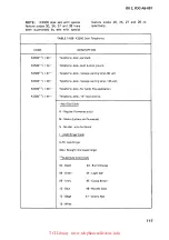
Страница 42: ...vides alphabetic and numeric codes for determining dial ringer and color selection TABLE 7 00 K500 Desk Telephones CODE DESCRIPTION K500 20 Telephone desk standard K500 24 Telephone desk push button g...

Страница 43: ...TCI Library www telephonecollectors info...

Страница 44: ...a The model K554 30 is a standard single line rotary dial wall telephone A wiring diagram for this model is shown in figure 8 01 b The model K554 34 is a single line rotary dial wall tele phone which...

Страница 45: ...I I f 1 I HOOKSWITCH I I I RD L Y I I RING SL a RCVR I I SL YL bl I I c I SL BN c I 0 I GN SL GR d I TIP SL WH e I BL I I J GN WH G1ll WH I SL RD f I SL BK g l I I WH y WH I RD I BK B I o L G I YL E1...

Страница 46: ...I RD RING I o I I I RCVR I SL a I I I SL YL _ b J I c I SL BN c 0 I I GN I TIP SL GN d PUSH I e BUTTON SL WH SWITCH WH _ I BL 0 R R I GN I WH GN I WH I SL RD f I SL BK g WH V I WH RD I BK B I I BK I Y...

Страница 47: ...e top of the housing places a holding loop across the opposite line to that selected by the turn and push key Installation 8 05 Wall telephones do not include a connecting block or mounting cord Insid...

Страница 48: ...SL J I RCVR I u I c I SL RD u RD J I I I I L _____J HOOKSWITCH WH RD LJ SL a RING WH SL YL b c SL BN cf 8 BK SL GN d SL WH e t XMTR o GJ YL F GN BL TIP RR GN J WH Glo SL RD f SL BK s1 RD WH BK II ABA...

Страница 49: ...YL SL RD I f I RD I r tiooi sw1Tc H 0iAL t I L SL a I I RCVR I SL YL b J I c c f I SL BN 0 c 0 I L1 SL GN d I t SL WH I v BL I ifR GR I WH G WH I SL RD f I SL BK g L I WH Y WH I RD I i BK I I QG I I X...

Страница 50: ...4 Telephone wall A lead control K555 30 Telephone wall 2 line with HOLD K558 30 Telephone wall 2 line Add Dial Code R Regular Numerals only M Metro Letters and Numerals N No dial e w dial blank Add Ri...

Страница 51: ...TCI Library www telephonecollectors info...

Страница 52: ...ine desk telephone equipped with a six con ductor mounting cord for pick up of two lines and push button signalling Model K510 I 36 9 04 The model K510 I 36 is the same as the type K510 30 except it i...

Страница 53: ...GR I I I I I t I GN GN TIP I I I I I I YL YL RING SL RD I I I I I t I RD _ RD RING I I I l COND I I I W r HOOKSWITCH DIAL SL a CORD I RCVR I ISL YL b I MOD 36 I I c I SL BN ct I 0 I 1 SL GN d t I SL...

Страница 54: ...cord K510 36 Telephone 2 line rotary dial 4 conductor cord Add Dial Code R Regular Numerals only M Metro Letters and Numerals N No dial e w dial blank Add Ringer Code LR Less Ringer BA Straight line b...

Страница 55: ...TCI Library www telephonecollectors info...

Страница 56: ...They are designed to be used with key telephone systems such as the ITT K1A2 system where several telephones have access to the same lines CO trunks or intercom lines 10 03 Five push button keys on t...

Страница 57: ...r BASE I Model K564 41 10 07 The model K564 41 is identical to the above model ex cept it includes a grounding push button switch The grounding push button is required in some PABX applications for tr...

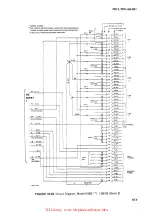
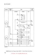
Страница 58: ...BN GN x BN BK HOLO KEY YL BN ISS 2 PDC AB 001 PU 1 7 1T lH L Ll E i LG PU 2 i i 2 I 7 2H 7 L2 u2 NE _Q__ PU 3 JR 3T 3H L3 u JL PU 4 4R 4T 4H L4 L NE Q__ 7 PU 5 5R r 5H L5 7 Ll 5 NEUL HOLD 7 FIGURE 10...

Страница 59: ...l to the model K565 40 telephone except it includes a grounding push button switch The grounding push button is required in some PABX appli cations for transferring calls originating calls during a po...

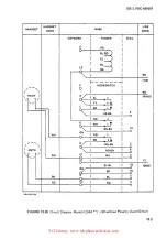
Страница 60: ...BN ll SL VI ON NETWORK SL YL SL ON I lB O WH l2 YL BN ON NETWORK YL I EXCL SW PU 1 I _1 R 1 7 H L1 Ll E f PU 2 2 2 f 2 l2 Ll 2 NEUl_ PUJ JR 3T 3H L3 Lt 3 NE _Q__ PU 4 4R 4T 4H l Ll E _Q__ PUS SB ST I...

Страница 61: ...11 The model K566 40 is the same as the model K564 40 except it includes a hookswitch restoration button which restores any operated line button when the hookswitch is depressed In addition this mode...

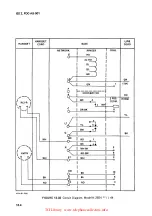
Страница 62: ...PU4 3 34 LG 4R 1Q Rl 4 J T 4 35 T TO SHEET 1 11 A11 l i G4H __ 36 A L NE llNE 12 L I l GN ON NETWORK i RR Vl GN I 7 BN VI 8 Vl BN L1 Sl V ON NETWORK 18 OR WH Sl GN L2 YL l NETWORK ION II A 99 110 001...

Страница 63: ...UX 6 ldl YL B YL BL 41 YL BL SIGS 3 OR YL OR YL bl 17 OR YL 4 4 YL OR YL ORlbl 42 YL OR HOLD LH HL GR YL GR YLlbl 18 GR YL LAMP LG HLG YL GR YL GRlbl 43 YL GR PB SIG SG SG BR YL BR YL BR YL 3 1 19 BRY...

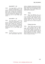
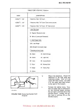
Страница 64: ...cable con ISS 2 PDC AB 001 nectars installation consists simply of plug ging the prewired connectors into the station cables Refer to the appropriate circuit diagram figure 10 01 through 10 03 and to...

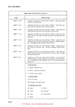
Страница 65: ...ch and additional contacts for hands free opera tion Equipped with 50 conductor cord with plug Telephone 6 button key with common HOLD rotary dial e w 34 conductor cord with plug Includes hookswitch b...

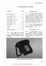
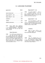
Страница 66: ...pe units which operate efficiently over a wide range of loop resistances and line impedances Each instrument consists of a pressed steel b se plate with four protective rubber feet All internal parts...

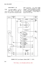
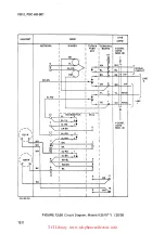
Страница 67: ...0 can be converted to a model K2500 24 by the addition of a ground ing push button switch Wiring diagrams for the model K2500 24 are shown in figures 11 01 and 11 02 LINE BASE CORD RINGER I DIAL YL I...

Страница 68: ...I f I HOOKSWITCH I W I SL YL a RD IRING 1 I I I I I I I I I SL b i I W o _ l t c_ l r J 0 1 J XMTR ABA80017 WH BK RD OR BK I 06 L1 I I I GN SL RD f I __ SL BK gi l I Y WH BK I 3 I I R D G N __ _ _l __...

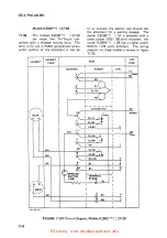
Страница 69: ...ing message The model K2500 27 is available with a lower power NE51 90 volt indicator the model K2500 28 has a higher power NE51H 125 volt indicator The wiring diagram for these models is shown in fig...

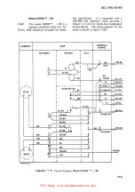
Страница 70: ...for hands ISS 2 PDC AB 001 free applications It is equipped with a 36G 450 dial assembly which provides a closure to mute the hands free loudspeaker during dialing The wiring diagram for this model i...

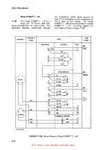
Страница 71: ...K2500 20 can be converted to a model K2500 44 A wiring diagram for this model is shown in figure 11 05 LINE BASE CORD RINGER I DIAL I GN VGNI I 1 TIP I I BK I SL c t K I I u A I SL RD I u I RD I I I...

Страница 72: ...ssage waiting lamp 90 volt K2500 28 Telephone desk message waiting lamp 125 volt K2500 39 Telephone desk for hands free application K2500 44 Telephone desk A lead control Add Dial Code R Regular Numer...

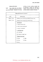
Страница 73: ...loudness control sidetone suppression circuit and any special features Check for noise due to loose contacts when the set is gently bumped or dropped Ordering Information 11 11 Because of the large n...

Страница 74: ...es The ringer is perma nently connected to line 1 a separate ringer must be provided for line 2 Model K2510 30 12 03 The model K2510 30 is a standard Tel Touch two line desk telephone equipped with a...

Страница 75: ...T IRD 1 RING RD I __________J 1 L2 HOOKSWITCH I DIAL SL a SL YL b L I c I ct I 4CONO SL BN CORD OR BK I 6 MOD 36 I 0 L1 I f RCVR SL GN d l__y SL WH I WH GN I 1 WH I 0 BK I 10 0 0 WH GN SL RD f I g J I...

Страница 76: ...s and their identifying numbers Because of the large TABLE 12 00 K2510 Desk Telephones CODE DESCRIPTION K2510 30 Telephone 2 line Tel Touch dial standard 6 conductor cord K2510 36 Telephone 2 line Tel...

Страница 77: ...TCI Library www telephonecollectors info...

Страница 78: ...of the set Series K2554 wall telephones use a type 148 miniature single gong ringer and a standard K500 type handset 13 03 Table 13 00 lists three variations of the series K2554 wall tele phones Inclu...

Страница 79: ...0 I I 1 I I RD __ y I SL a I 2POS RING I YL b I TERM I tc I BN CJ I GN d I I WH e I I GN 1 0 c I OR BK 6 0 0 WH _ N I RD f I g J BK I y I WH BK 3 I I RD GN XMTR I I WH E1 I WH 2 1 I YL RR I BK 10 GND...

Страница 80: ...l TIP F HOOKSWITCH 0 I RD RCVR I A RING 1 SL a VL b J c BN cf UR BK 6 0 GN d G WH e f BN BK 19 GN 0 WH RD f 9 J BK L_ WH BK 3 I I XMTR I RD GN 8 I E1 WH WH 8 VL SL BL 18 GND BK o BK 5 BL RD E 2 RD 4...

Страница 81: ...I F 0 i HOOKSWITcH A RD I I 2 POS RING RCVR GN d TERM I te wHI CJ 1 c I OR BK I 6 0 I 0 I YL I L1 I YL I BN d G rt _ I BK WH GN I RD f I g i BK R 3 I WH BK I XMTR I I RD GN 8 WH E1 I WH 2 I I RR I 10...

Страница 82: ...e 05 Green 44 Light Ash 09 Ivory 45 Cocoa Brown 12 Blue 46 Harvest Gold 13 Beige 47 Cherry Red 15 White b Mount the telephone Attach the telephone to the wall using two mounting screws One is in the u...

Страница 83: ...and release the retainer Testing 13 06 After the telephone set is in stalled check for proper operation of the Tel Touch key pad transmitter receiver ringer loudness control sidetone suppression circ...

Страница 84: ...stems such as the ITT K1A2 system where several tele phones have access to the same lines CO trunks or intercom lines 14 03 Five push button keys on the tele phone are used for line trunk or intercom...

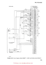
Страница 85: ...t includes a grounding push button switch The grounding push button is required in some PABX applications for transferring calls originating calls during a power failure etc TERMINAL BASE BOARD T RING...

Страница 86: ...KEY OR WH Yl BN ON NETWORK Ll 3 l Ll E 1 LG 7 f i f 2H L2 Ll ElQ__ i JR JT LJ L1 3 NElQ_ 4R 4T L4 l NE _ SR 5T 5H L5 LIN j __ 5 L HOLD s 7 28 LG 4 NY _ R l 29 T l1NE 5 A1 1 2 30 A I s LI 31 LGj 7 Rl 3...

Страница 87: ...TO SHEET 2 PUSH BUTTON I HOOKSWITCH I 5 94 1 L lt lgi 1 I I tc ISL BNCJ 2 POS I c I OR BK I 6 TERM I R I I I 0 I GN I 0 I F l I 1 L __ __ GN GN ISL RD I I SL BK g R IRD GN I WH BL L1 0 L2 I I I I I YL...

Страница 88: ...KEY STFllP TERMINALS MOUNTING COFID I 1 caNNECTOFIP N 1 L L u 211 IT 2 Li Lii r y 3H L3 4R 4T 4H L4 SH ST r S LS F f 7 21 T LINE Z r A1 1 27 A 3 L 21 T L l il _ LINE I A1 2 30 b A I cl L L B A1 3 A LI...

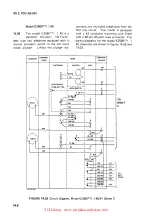
Страница 89: ...ing the plunger dis 14 6 HANDSET HANDSET CORO BASE I I I RINGER DIAL I Roi lsL RD J I G c I K I SL I NETWORK TERMINAL BOARD R JBKi T GROUNDING f ___ _ L_ _ 0 l PUSH BUTTON LHOOKSWITCH I i q b S Y s 1...

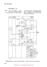
Страница 90: ...SETS ARE CONNECTED IN MULTIPLE THROUGH BAIGING ADAPTERS RR SL YL 11 I N I TO SHEET RT YL SL BL YL ____ GN _____ ION NETWORK I A HIB0003 EXCL SW PU 1 PU 3 PU 4 EXCL SW ISS 2 PDC AB 001 EXCL PHONES FIGU...

Страница 91: ...I I NETWORK J RINGER J DIAL I ROI SL RD I TERMINAL BOARD R I SL I BK RT Hu i N f 1 H_Qp S _IT 1 _ L L i 2PO I 6 I OR BK I TERM I R_ l I I I I GN I i___x I GN I GN lsL Ro 1 I lsL BK 9 Y IRD GN I IW_H_...

Страница 92: ...MINALS MOUNTING CORD rrCONNECTORPINS PU 1 PU 2 PU3 PU4 PU 5 EXCL SW I L J 26 T 2 A1 LrE 1 H L1 Ll E O Ljl 2 1 2T 27 A L G 29 T 6 tL_ A1 Ll E 2H L2 LliEUL 3R 3T 30 A l L 31 L_ LG 32 T 7 Rl B Al LINE 3H...

Страница 93: ...s elephone arranged for hands free ap lications It is equipped with a 2500 00G type Tel Touch dial assembly which pro vides a closure to mute the hands free speaker during dialing and an additional HA...

Страница 94: ...S EXCL SW ISS 2 PDC AB 0 01 EXCL SW I ITKEY STRIP TERMINA S MOUNTING CORD rr CONNECTOR PINS 1 L 1 T i i L1 LINE 1 LG 2T 2H Li LINE 2 LG 3 3 3H L3 LINE 3 LG 4R T F L4 F LINE 4 LG SH SH L6 LINEco n 5 LG...

Страница 95: ...also includes an additional push button for recalling the attendant or for transferring a call in some PABX applications 14 12 Installation 14 14 As these telephones are equipped with quick connect ca...

Страница 96: ...additional contacts for hands free operation Equipped with 50 conductor cord with plug Telephone 6 button key with common HOLD Tel Touch dial e w 34 conductor cord with plug Includes hookswitch butto...

Страница 97: ...TCI Library www telephonecollectors info...

Страница 98: ...with two 50 pin 25 pair male connectors 15 04 The red button on each unit serves as a HOLD key it is used to place one or more lines on hold The remaining buttons are used as line pickup keys they may...

Страница 99: ...42 except it is equipped with a push button switch for operator recall g h 15 09 a b c See figures 15 01 and 15 05 for wiring diagrams The model K2830 76 is the same as model K2830 42 ex cept it is a...

Страница 100: ...I I d GN I CJ c I DIAL ISS 2 PDC AB 001 TERMINAL BOARD SL YL R1 TO FIGURE 15 01 OR 15 08 YL SL 29 OR WH GN W i RD RD B1 A1 R R 0 I WH I I LL ______ _ _ ______ LG _ __ _ _ __ 23 WH GN WH WH WH BK g B R...

Страница 101: ...46M 5 CONDUCTORS TAPED 8 STORED f T j 1 1 _ r i lf l _ _f _ _ h_ i 1 t _J t i i c 1 I JJ I 4 Ir i o jlf li 1 J 1 a o 1 I l h 1 I kl llllNCilR i i z _ i L Z 0 a 1 I 0 J _ z 1 _ 1 I l _ E _ r r l 0 tr I...

Страница 102: ...I 0 i c I BN L2 I YL OR BK 0 I YL I 3J WH BL d I GN WH c I WH 0 18 GN WH WH 9 N WH GN T RD f 1v GN T WH BK g RD GN WH r RD BK RD R B GN RD R BL T WH _ F 1 I RD GN iCMTII I I J RD WH A17 I I 3 I I BL...

Страница 103: ...USED ClN TIE K1 A KSU AND CAU AfN l lrlCERS ARE NOT USED REFER 10 ICSP K76AW IOI FOR lDCATION OF 24V BATTERY 10 USE WITH 76M TELEPHONES TO CONNECTOR r N _ 1 en 0 N f o0 J 1 1 0 f r r r r l 0 c J c J...

Страница 104: ...Bl f 1 I HOOKSWITCH I SL 29 a I L1 I Lb I YL iloR W Al 0 I RCVR I c I BN GN WH L2 I I c 0 I b I I t I I I I d I GN RD R C WH I I 0 I I WH GN I WH I DI f I _ WH BK I ai I I R I I RD WH I BK A I I t R...

Страница 105: ...a SL I 29 I L b YL I 1 _0R WH Al F I c BN I GN W 0 I d GN I rRD R OPERATOR IWH e t I RD R G _ 1 28 jlJ rGN I GN WH I 16 I I I OR BK I 6 I 0 GN I I I 4 _J WH GN RD f gl BK R_ RD GN 3 RD L2 RD 4 BK B B...

Страница 106: ...R I I GN I I I OR BK I I I GN 6 WH d TO IWH e t I FIGURE I GN WH I 16 15 03 OR I OR BK I 6 15 09 I 0 18 GN GN WH L1 I 2 WH WH GN I WH RD f GN T g l I _y BK GN T A RD GN I 3 RD GN RD L2 RD I RD R BK 8...

Страница 107: ...ISS 2 PDC AB 001 FIGURE 15 07 Circuit Diagram Model K2854 15 10 TCI Library www telephonecollectors info...

Страница 108: ...m 1_w u 11m u tJ Y ll lll ll lll1 ll t J1 ir c i 1 I i J 1 r w 1 i J _J I t r l _ i_ __ l1Lt Aw 11 I 1 1 Lf J 1 5 I I I 0 Til4B1 i L zo I lt 2 I __ lJt J I I I f I I I I ll li t I 1 0 J 1 i 1 1 i J 4...

Страница 109: ...D ON CONNECTOR PLLIG 6 wt N 76M TELEPHOHl S ARE US 0 ON THE tl 76A KSU AMI l E v lr SET TO CONNECTOR NO 2 1 filllmi lU llHflllll 1 1 I l l j Ji_ i J J 1 1 I ll HrI1 1WJkfl 1WlkUflWIDI MlkUMUHr1 Ulrnff...

Страница 110: ...dditional set of contacts in the hookswitch for ON OFF control of hands free equipment Circuit diagrams for the model K835 42 are shown in figures 15 00 15 01 and 15 10 The model K835 46 is the same a...

Страница 111: ...TON KEY TELEPHONE INCLUDING SETS WITH OPG PADS H DIODE STRAP I 2 PICKUP KEY N OR 6 _A_l i i d s_L_ _G_R_N l 2 REMOVE BUZZER LEADS CONNECT ELSEWHERE HOOKSWITCH CONTACT MOVED FROM N TERM ARA 80 041 FIGU...

Страница 112: ...37 G BK A 13 G BK R 13 Line 5 BK G T 38 Une 14 BK G T 38 Slate BK BR Aor S 39 Slate BK BR AorS 39 Plug S BK L 15 Plug S BK L 15 BK S LG 40 BK S LG 40 BL Y A 16 BL Y R 16 Line 6 Y BL T 41 Line 15 Y BL...

Страница 113: ...ept Code 76 WIRE COLOF REMOVE NNECTTO OR FROM GUARD NET LEAD NETWORK ASSY WORK Dial BK RR T G W c s Line Switch w c s Guard G RR Assy w c NOTE Order Polarity Guard Stock No 91221 e Manual signalling c...

Страница 114: ...y Conversion For 20 Button Sets CONVERSION 1B1137 102 KEY LEADS OPTION NOTE 0 W S W G R BL BK BR BK BK BR BK BL R G W S V BR PPPPPPPPPP 19 19 19 23 23 23 26 26 26 26 PPPPPPPPPS 19 19 19 23 23 23 26 26...

Страница 115: ...TCI Library www telephonecollectors info...

Страница 116: ...m an alternating current source The sensitivity is such that satisfactory operation is obtained on the longest circuits _ the high impedance prevents excessive bridging and unbalance loses Most of the...

Страница 117: ...protected by a molded plastic housing External connections are made to a terminal block enclosed in the unit The assembly is equipped with a mechanical volume control 16 2 Type 148A Ringer 16 06 The...

Страница 118: ...3 Two 3 inch polished gongs on the unit serve as the ringer or chime Each gong produces a different tone In the ringer mode the gongs produce a ring ing sound in response to the applied ringing signal...

Страница 119: ...e such that the control lever is within reach and enough clearance is provided to tighten the top cover screws The unit fastens directly to the wall with two fasteners of sufficient length to provide...

Страница 120: ...locations 17 12 The unit consists of a wall bracket which supports a horizontal base plate on which two 4 inch diameter gongs and a ringer mechanism are mounted The gongs mount at the bottom of the ba...

Страница 121: ...nging bell is shown in figure 17 04 For a listing of replaceable parts refer to the ITT TIMM 2 Telephone Instrument Maintenance Manual 17 4 t CAPACITOR ABA 80 049 TO LINE FIGURE 17 04 Wiring Diagram T...

Страница 122: ...equip ped with leads Instead male tabs are pro vided to accept female snap on terminals Series 30 Rotary Dial 18 05 Series 30 rotary dials are manu factured by ITT for use in stand ard ITT telephone...

Страница 123: ...IAMETER METRO b c 91161 The type 33 rotary dial is a minia ture type for model K700 and similar sets which have a 3 inch diameter opening in the housing It has one set of off normal contacts to short...

Страница 124: ...down on the paper clip to spring the tab of the retainer clip Rotate the finger wheel clockwise to release it Work the finger wheel off the retaining clip and remove it from under the finger stop See...

Страница 125: ...ering Information Tel Touch Dials CODE DESCRIPTION PART NO 32 G 450 12 Button Metro Style 61363 Tel Touch Dial 32 G OPG 12 Button Metro Style Tel 61530 Touch Dial with Polarity Guard 36 G 450 12 Butto...

Страница 126: ...ie1 2 k 111 1 3 i k tho 4 5 i k loot Cl1i I not _ ot111 1rv I i ISS 2 PDC AB 001 operates The switch spring assembly causes the following to occur a Attenuates side tone in the re ceiver to a compatib...

Страница 127: ...otted Iines represent cranks and slide Springs 6 7 break first then in succession the 1 2 10 11 springs make and then the 1 3 8 9 springs break The 4 5 springs break last ABA 80 054 0 Cl FIGURE 18 04...

Страница 128: ...043 urn 1 NI g 1 1 r t 1 j C I I a I UFO 03 U _6 o l _ _ L __ Z ABA 80 055 L _ SL OLARITY GUAllD Ol TIOfll CR A CR6 l I I I FIGURE 18 05 Wiring Diagram Type 36 Tel Touch Dial with Polarity Guard Circ...

Страница 129: ...18 8 NOTE Sets which include a Tel Pulse dial are designated by T in the telephone code number suffix For example K2830 0BA 40T 18 20 For field installation the mount ing kits shown in table 18 02 mus...

Страница 130: ...her to attach the printed circuit board and the insulator to the left dial mounting bracket SCREW No 6 32 x 3 8 SPRING WASHER _ ABA 81 014 DETAIL A K2500 TYPE SETS ISS 2 PDC AB 001 3 Install the key p...

Страница 131: ...hite to network terminal RR 5 Move the white and red handset cord leads from ter minals 10 and 11 of the auxiliary terminal board to network terminal R Move the white hookswitch lead from network term...

Страница 132: ...101 in cluded in the mounting kit P C BOARD ABA 81 014 d ISS 2 PDC AB 001 K2576 three line desk sets 1 Remove the telephone face plate housing Tel Touch dial and ringer if the set is so equipped 2 Re...

Страница 133: ...jfj MOUNTING BRACKET 4 Install the printed circuit board under the 10 button key assembly Secure it to the mounting bracket using the two 6 32 x 5 16 inch screws 5 Connect the Tel Pulse dial leads as...

Страница 134: ...e Rate lnterdigital Timing Strapping PULSE RATE 1OPPS Green to E1 20PPS Green to E2 INTERDIGITAL INTERVAL AT 10PPS 400MS Blue to E1 BOOMS Blue to E2 Interval for 20PPS is 1 2 interval for 10PPS ISS 2...

Страница 135: ...TCI Library www telephonecollectors info...

Страница 136: ...shown in figure 19 00 All com ponents mount on the underside of the 0 IQ DER TERMINALS ll ICll W TEllM S 11 1 ATIVE IN8 DOOECTION OP TflANIFORMER COILS ABA 80 057 F DIAL LUE CGNtaCTI RADIO FIOEQUEllC...

Страница 137: ...19 02 19 05 Push on and screw type terminals on the printed circuit board will accommodate up to four lugs per terminal Additional connections can be made to terminals L1 L2 and G Two extra ter minal...

Страница 138: ...ng blocks is dependent upon wheth er the cables enter the equipment room from above or below the backboard Where cables enter from below the blocks are usually mounted toward the bottom of the backboa...

Страница 139: ...doffs which in turn attach to POWER SUPPLY ABA S0 060 KSU I FEEDER the backboard Screws for attaching the connecting blocks to the standoffs are contained in the standoff packages Connecting Block Sta...

Страница 140: ...s for the middle connect ing block This difference is due to the fact that the upper and lower standoffs for the middle connecting blocks are shared by the top and bottom blocks c d e f ISS 2 PDC AB 0...

Страница 141: ...0 7 8 33 1 8 27 5 8 39 5 8 34 1 8 46 40 1 2 ABA 80 061 TOP EDGE OF BACKBOARD 1 2 TYP _ I u u DIMENSIONS IN PARENTHESES ARE USED WHEN D RINGS ARE MOUNTED AT BOTTOM OF BACKBOARD FIGURE 20 02 Backboard L...

Страница 142: ...busy line can be placed on hold by op erating the HOLD key on the key telephone set When the HOLD key is depressed ground is disconnected from the A lead and a holding bridge is placed across the line...

Страница 143: ...our conductor line cord as follows 1 Connect the red RING lead to network terminal L2 2 Connect the green TIP lead to network terminal F 3 Connect the black A1 lead to network terminal L1 4 Connect th...

Страница 144: ...s necessary to provide a non locking push button switch at one telephone to control a buzzer or similar device on a remote telephone An unassigned line pick up key an external switch or a switch mount...

Страница 145: ...H BUTTON GROUND ADD STRAP AT MDF ANO REMOVE LOCK ING SCREW STRAPATMDF n CONNECTOR 2 USE OR BINDER A GRDI NOTE TO CONVERT KEY FOR LINE 19 TO PUSHBUTTON GROUND ADD STRAP AT MDF AND REMOVE LOCKING SCREW...

Страница 146: ...02 show call transfer key modifications for various types of tele phones NETWORK c 0 NETWORK PUSH BUTTON b TRANSFER KEV WIRING K564 K565 PUSH BUTTON c TRANSFER KEY WIRING K576 K577 ISS 2 PDC AB 001 D...

Страница 147: ...cautions 21 11 Observe the following notes and precautions when performing the above modifications a Installation notes 1 All holes for keys shall be 1 4 inch diameter 2 Before drilling holes remove t...

Страница 148: ...CH ABA ao 071 a RINGER CUT OFF KEY LOCATION TOGGLE SWITCH G NETWORK b RINGER CUT OFF KEY WIRING K500 REMOVE TO TERMINALS T R OF SELECTED LINE KEY TERMINAL BOARD ON KEV TERM BOARD c RINGER CUT DFF KEV...

Страница 149: ...g all keys dress the slack in the connecting wires to prevent wires from interferring with the hook switch or ringer Material List 21 12 Table 21 00 lists the materials needed for the above modifi cat...

Страница 150: ...TABLE 22 00 Ordering Information Buttons and Buzzers DESCRIPTION STOCK NO Button Push 1 Button Beige 91900 Button Push 1 Button Black 91906 Button Push 1 Button Green 91669 Button Push 1 Button Ivory...

Страница 151: ...2 00 SE 7F Buzzer 22 05 The type SE 7F buzzer is shown in figure 22 01 It is equipped with a plastic cover and is designed for use as an external signal device Including the cover it measures approxim...

Страница 152: ...ABA80072 FIGURE 22 03 Typical Button and Buzzer Circuit ISS 2 PDC AB 001 22 09 Detail A of figure 22 04 shows wiring of a button and buzzer circuit using an external push button for the signaling key...

Страница 153: ...ERNAL PUSH BUTTON OR YL YL OR BK BN BN YL KEY STRIP TERMINALS J 4 SH x SG BN BK B z NOTES 1 Move BK BN lead from terminal X to SG 2 Terminals shown are peculiar to Model K25S5 39 42 Key Telephone ABA...

Страница 154: ...1 11 26 26 26 26 HPPPPSSSSS 7 7 7 11 26 26 26 26 26 NOTE Connect 0 Y mounting cord lead to terminal 26 TABLE 22 03 Pickup Signal Key Conversion For 20 Button Sets CONVERSION 181137 102 KEY LEADS OPTIO...

Страница 155: ...TCI Library www telephonecollectors info...

Страница 156: ...d for surface placement or fixed mounting using wood or metal screws and may be used with exposed or concealed wiring 23 03 Bases for type SE 15 SE 17 and SE 18 lamp assemblies will accept standard 6...

Страница 157: ...IGURE 23 02 SE 21 Indicator Lamp 23 2 Ordering Information 23 06 Ordering information for the lamp assemblies described in this sec tion is provided in table 23 00 TABLE 23 00 Ordering Information Lam...

Страница 158: ...has 8 screw terminals which are pre wired to the connector Wires in the station mount ing cord connect directly to the screw terminals A slit or trough in the terminal strip accommodates the mounting...

Страница 159: ...TCI Library www telephonecollectors info...

Страница 160: ...ale connector is used to connect the 6040 key to the station cable serving the assigned single line telephone The 6040 key is shown in figure 25 00 25 02 A terminal strip mounted on the top of the key...

Страница 161: ...onnected to the key strip terminals connecting the 6040 key to a model K554 30 wall telephone 25 2 5 4 3 2 HOLD 0 0 i 0 l 0 i 0 i 0J le _ 0J 0J sc0J c0J c0J c0J ceJ i i 0 0 0 0 0J 0 z 0J tn _0 0 0 i 0...

Страница 162: ...ABA B0 075 6040 KEY ET FIGURE 25 02 Telephone Set Connections 6040 Key to K 554 Wall Set QUAD WIRE GN K 2554 TEL SET L2 a Modify K 2554 for A lead control See paragraph 21 06 ER RED A b Move the black...

Страница 163: ...BN WH 4 OR YL 2T WH BN 2H Wf 1 SL M L2 BL RD N LG RD BL RR SL YL RT YL SL 3R OR RD 5 GN VI 3T RD OR 6 Vl GN 3H RD GN ONI BN VI L3 BN RD ON LG RD BN R 4R SL RD SL WH 4T RDSL GN RD 4H BK BL BL BK L4 OR...

Страница 164: ...red separately Speakerphone Operation 26 03 The PC 4A speakerphone incor porates a voice switching cir cuit which permits a substantial increase in receiving volume eliminates singing and essentially...

Страница 165: ...ring Information ITEM STOCK NUMBER WH ITE BLACK GREEN BEIGE COCOA ASH BRN LOUDSPEAKER PC 108A 61462 61460 61461 61459 61528 61534 TRANSMITTER PC 680A 61458 61456 61457 61455 61529 61533 TRANSFORMER PC...

Страница 166: ...be heard over ISS 2 PDC AB 001 the loudspeaker The ON lamp will ex tinguish and remain so for as long as trans mission is disabled Release the ON or OU IET button when you wish to again transmitt to t...

Страница 167: ...the loudspeaker cable should point to the option required on the option plug COMMoN COVER PC 182A Connecting Block 26 15 The PC 182A connecting block is used in place of the PC 82A connecting block It...

Страница 168: ...al make contacts if the c d ISS 2 PDC AB 001 handset will be left on hook during dialing These contacts are required to mute the loudspeaker and receiver during dialing The dial common switch in a Tel...

Страница 169: ...URE 26 02 PC 4A Speakerphone Arrangement Telephone Served by Connector Cable NOTE 26 6 PC 182A CONN BLOCK PC 108A LOUOSPEAKE R SET TELEPHONE SET ROTARY DIAL OR TEL TOUCH PC SSOA TRANSMITTER FIGURE 26...

Страница 170: ...n in figure 26 03 ISS 2 PDC AB 001 b Connect the telephone set to the connecting block If the mount ing cord is plug ended plug in the connector as shown in figure 26 03 If the mounting cord has spade...

Страница 171: ...wiring and LK leads for open released Rotary dial pulses heard over Dial wiring For proper dial P3 and P4 loudspeaker leads No dial tone heard when speaker Open wiring R1 and T1 leads from tele phone...

Страница 172: ...speaker is used in the normal manner the handset must be off hook to use the loudspeaker The ON OFF VOLUME control on the front panel is rotated clockwise to turn the unit on and to increase the volum...

Страница 173: ...ctor mounting cord will be required to connect the loudspeaker 27 07 Figures 27 01 and 27 02 show typical connections for the K 107A loudspeaker K 31 A 690 TRANSFORMER ORDER SEPARATELY NOOK UP IW CABL...

Страница 174: ...NDUCTORS I CONNECTING BLOCK 0 IN MOUNTING CORO c__ 0 NOTE 1 In Key Systems Use the Key System Power Supply and Spare Conductors in the Power Supply Cord Otherwise Use K 31 Al690 Transformer and IW ABA...

Страница 175: ...TCI Library www telephonecollectors info...

Страница 176: ...stems are described in the following paragraphs Power Supply 28 03 The choice of a power supply when installing a key telephone system is of primary importance The selected supply must be sufficient t...

Страница 177: ...ial intercom Each KSU Key Service Unit consists of a backboard as sembly an equipment mounting frame and a cover The backboard assembly includes 2 quick connect terminal blocks which provide convenien...

Страница 178: ...the power supply 28 11 a b System capacity and features Maximum of 6 CO PABX or manual intercom lines Manual or dial selective 9 or 19 station intercom c Lamp signals 1 Idle line lamp extinguished 2 B...

Страница 179: ...ouncing on an intercom In systems where ringing current is required a ringing generator is available The ringing generator attaches to the back board by means of six screws it connects to the power su...

Страница 180: ...4243 101 Call Announcing Card 183973 101 184246 101 Tel Touch Adapter for Dial Intercom 183981 101 184247 101 CO PBX Line KTU K 400E 000400 00E KSP400 00E Manual Intercom KTU K 401 B 000401 008 KSP401...

Страница 181: ...s 3 7 8 inches wide 7 inches high and 2 5 8 inches deep It is equipped with a card retainer secured to the top or bottom of the front panel with two machine screws 28 6 FIGURE 28 03 K 2598 2 Card Pane...

Страница 182: ...KTU connectors 11 13 28 29 Three standard 25 pair cables are used to connect the 50 pin cable connectors on the K 584C panel to type 66 connecting blocks Connector 1 is cabled to key block A connector...

Страница 183: ...or PBX t i CO or PBX BK BL CO or PBX BK BL BL BK BL BK BK 0 BK 0 BK 0 0 BK 0 BK 0 BK BK G BK G BK G LINE G BK LINE G BK LINE G BK 3 G BK BR B BK BR 13 BK BR BR BK BR BK BR BK BK S BK S BK S S BK S BK...

Страница 184: ...TIONS E W INTERRUPTER USED ALONE PROGRAM A POWER SUPPLY CONNECTIONS See Notes Below See Note 3 NOTES ABA 80 084 POWER SUPPLY A GND A BATT 24 VDC Filtered B GND B BATT 24 VDC Ringing GND Ringing Voltag...

Страница 185: ...0 INTERRUPTER __ 5 ___________ 5 __ 7 7 3 3 __ 1 1 40 ___________40 __ 43 __16 20 __ 9 18 __ 20 __ 18 26 26 __ 37 21 23 29 31 28 22 2 5 27 33 35 28 22 TO 44 30 26 2 Remove factory strap between 11 and...

Страница 186: ...busy idle ringing etc of the associated line It provides the circuitry for control of the following visual and audible signals a b c ISS 2 PDC AB 001 Lamp flash on incoming calls Lamp steady on answer...

Страница 187: ...Factory Strapping 1 1 2 1 2 w Interrupted ringing Factory Strapping 1 5 8 5 8 T Steady ringing 1 6 8 6 8 v Auxiliary Common Audible signal control 1 4 8 4 8 y Winking lamp on hold Factory Strapping 1...

Страница 188: ...e input to accept the output of a tape deck tape player or other low level music source and six isolated ISS 2 PDC AB 001 outputs for supplying music to as many line circuit KTU s A schematic of the K...

Страница 189: ...not removable hence maintenance is limited to replacing the entire unit in the event of a failure The RT 1900 dial intercom unit is designed for wall mounting or for standard KTS rack mounting It mea...

Страница 190: ...legend on the side of the unit Make the power supply con nections shown in table 28 05 Multiple the tip T and ring R leads of each station line and cross connect to the Tl P and RING terminals on the...

Страница 191: ...ON 2 INTERCOM PICKUP KEY T A G LAMP B BUZZER OR BELL STATION 3 INTERCOM PICKUP KEY T LAMP R G B BUZZER OR BELL WHEN INTERCOM AUD SUP 18VAC AUDIBLE IS SEIZED 1 110VAC 30Hz SUPPLY I I 18o I RO I l _ B _...

Страница 192: ...CR7 tl 177 249 LI 10 1 3 3K CRB CR9 LED FIGURE 28 13 Circuit Schematic K 400E KTU r 12 T r 3 GND t I t 11 J 4 110v L 8 L r11 r11 4131 18 24V A FIGURE 28 14 Circuit Schematic K 401 B KTU BATT B I 28 17...

Страница 193: ...c uf 7 2 1 2 w soon ___ _ c 4 0047ull I r __J 1sn T l R3 12V QI Rl2 RIO 910fi 2 2 K R4 I I I 5 1 1 2 13 1 2 w 24 v 7 2 14 TS R5 r 15 240fi ti I I AG r Rl4 1 U l l L 1 2 w I K 16 lc3 j I j Tl Out TI R6...

Страница 194: ...made up of a series of diodes connected in the ring lead between the KTU line card and the associated telephone The diodes are selectively connected in the station ringing leads to pass ringing curre...

Страница 195: ...ystem connecting block to the diode matrix connecting block as follows 1 Connect the R1 lead to the anode side of the first diode If necessary multiple the lead to any other re quired diode s Where th...

Страница 196: ...G BLOCK TOCO OR PBX TO STATION CONNECTING BLOCK ISS 2 PDC AB 001 DIODE MATRIX CONNECTING BLOCK 66B3 50 LINE 1 LINE 2 LINE3 SCHEMATIC LINE 1 RINGS STATION 1 2 LINE 2 RINGS STATION 1 2 3 LINE 3 RINGS ST...

Страница 197: ...TATION CONNECTING BLOCK DIODE MATRIX CONNECTING BLOCK 66B3 50 R1 STATION 1 R1 STATION 2 R1 STATION 3 R1 STATION 4 LINE 1 R1 STATION 1 R1 STATION 2 LINE 2 R1 STATION 3 LINE 3 R1 STATION4 LINE 4 SCHEMAT...

Страница 198: ...of 10 outputs 1 10 Connections are made by inserting pins into the block at selected locations Two types of pins are available a shorting pin 5214 L4 used for common ringing assignments and a diode pi...

Страница 199: ...ONNECT R1 B1 25PAIR CABLE C 25 PAIR MATRIX CONN BLOCK A li N CA MATRIX BLOCK ASSEMBLY A N 1 10 STATION BLOCK R1 Bl CROSS CONNECT FIGURE 29 04 Cabling Scheme for Matrix Block Assembly PART OF TEL SET C...

Страница 200: ...Performance Development Center ITT TCI Library www telephonecollectors info...

Отзывы: