Section 13.0 Appendix D: DeviceNet Gateway Option
HGA IOM
128
Setup
•
Connect Anybus gateway on the HMI assembly using a DeviceNet cable to the 1770 Allen
Bradley KFD.
•
Connect the 1770 Allen Bradley KFD to the 1769 DeviceNet Scanner using another DeviceNet
cable.
•
Attach the 1769DeviceNet Scanner to the ML1500 PLC using the pin header present on the
scanner; similarly attach the bus terminator cap to the other end of the scanner to finalize PLC
assembly.
Figure 79: DeviceNet Network Setup
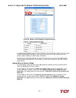
Establishing Correct Network Settings
The baud rate and node address are two important aspects of DeviceNet network, a mismatch in
baud rate or a clash of node addresses will produce a red network status LED on the DeviceNet
devices. The baud rate and node address for the three network devices can be set as following:
1.
Anybus Gateway
– The gateway is equipped with 8 switches, as described in the appendix
DeviceNet network section. These switches can be manipulated, as descried to match network
baud rate and provided the gateway with a distinct node address.
2.
1770 KFD
– The network settings and node address for the KFD are set in RSLinx. The RSLinx
software is used to obtain nodes in a network. The KFD provides RSLinx the access to the
DeviceNet network nodes.
3.
1769 DeviceNet Scanner
– The network and baud rate settings for the scanner are given on page
40 of the DeviceNet Scanner Module
(http://literature.rockwellautomation.com/idc/groups/literature/documents/um/1769-um009_-en-
p.pdf).
Once the corrected baud rate and individual node addresses are assigned for the devices on the
network, the network and module LEDs on each device should be green.
Содержание HGA HarmonicGuard Series
Страница 26: ...Section 4 0 Pre installation Planning HGA IOM 19 Figure 3 Altitude and Ambient Temperature Derating ...
Страница 40: ...Section 5 0 Installation Guidelines HGA IOM 33 Figure 11 HGA 480 V Two Unit Parallel Connection Diagram ...
Страница 42: ...Section 5 0 Installation Guidelines HGA IOM 35 Figure 12 HGA 480 V Three Wide Parallel Unit Connection Diagram ...
Страница 47: ...Section 5 0 Installation Guidelines HGA IOM 40 Figure 16 HGA 480 V Main Tie Main Connection Diagram ...
Страница 48: ...Section 5 0 Installation Guidelines HGA IOM 41 Figure 17 Current Transformer Diagram Round ...
Страница 49: ...Section 5 0 Installation Guidelines HGA IOM 42 Figure 18 Current Transformer Diagram Rectangular ...
Страница 76: ...Section 7 0 HMI Introduction HGA IOM 69 HMI Installation Diagram ...
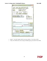
Страница 138: ...Section 13 0 Appendix D DeviceNet Gateway Option HGA IOM 131 Figure 80 Ladder Diagram Observing HMI Status ...


