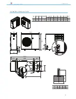
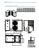
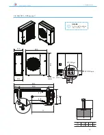
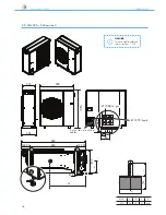


ANL - ANLH 020-202
27
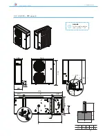
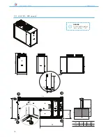
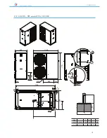
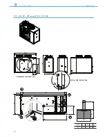
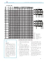
6. ELECTRICAL DATA / 7.ELECTRICAL POWER SUPPLY CONNECTIONS
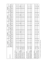
6. ELECTRICAL DATA
2
]
2
]
2
]
°
1
1
59,5
16,5
1
1
4
2
0,5
4
25
P
1
1
26,5
17,5
1
1
4
2
0,5
4
25
°
1
1
62,5
16,5
1
1
4
2
0,5
4
25
P
1
1
63,5
17,5
1
1
4
2
0,5
4
25
°
1
1
83,7
19,7
1
1
6
2
0,5
6
25
P
1
1
84,7
20,7
1
1
6
2
0,5
6
25
°
1
1
98,7
23,7
1
1
6
2
0,5
6
32
P
1
1
99,7
24,7
1
1
6
2
0,5
6
32
°
1
1
26,5
6,0
3+N
1
2,5
4
0,5
2,5
16
P
1
1
27,5
7,0
3+N
1
2,5
4
0,5
2,5
16
°
1
1
32,5
6,0
3+N
1
2,5
4
0,5
2,5
16
P
1
1
33,5
7,0
3+N
1
2,5
4
0,5
2,5
16
°
1
1
35,7
6,7
3+N
1
2,5
4
0,5
2,5
16
P
1
1
36,7
7,7
3+N
1
2,5
4
0,5
2,5
16
°
1
1
48,7
8,7
3+N
1
2,5
4
0,5
2,5
16
P
1
1
49,7
9,7
3+N
1
2,5
4
0,5
2,5
16
°
1
2
65,3
11,3
3+N
1
4
4
0,5
4
16
P
1
2
67,3
13,3
3+N
1
4
4
0,5
4
16
1
2
68,0
14,0
3+N
1
4
4
0,5
4
16
°
1
2
75,3
13,5
3+N
1
4
4
0,5
4
16
P
1
2
77,3
15,5
3+N
1
4
4
0,5
4
16
1
2
78,0
16,2
3+N
1
4
4
0,5
4
16
°
1
2
102,3
16,3
3+N
1
6
4
0,5
6
25
P
1
2
104,3
18,3
3+N
1
6
4
0,5
6
25
1
2
105,0
19,0
3+N
1
6
4
0,5
6
25
°
1
2
96,3
17,3
3+N
1
6
4
0,5
6
25
P
1
2
98,3
19,3
3+N
1
6
4
0,5
6
25
1
2
99,0
20,0
3+N
1
6
4
0,5
6
25
°
2
2
76,0
22,0
3+N
1
10
4
0,5
10
25
P
2
2
77,4
23,4
3+N
1
10
4
0,5
10
25
2
2
78,8
24,8
3+N
1
10
4
0,5
10
25
°
2
2
87,0
26,0
3+N
1
16
4
0,5
16
45
P
2
2
89,8
28,8
3+N
1
16
4
0,5
16
45
2
2
90,5
29,5
3+N
1
16
4
0,5
16
45
°
2
2
117,0
34,0
3+N
1
16
4
0,5
16
45
P
2
2
119,8
36,8
3+N
1
16
4
0,5
16
45
2
2
120,5
37,5
3+N
1
16
4
0,5
16
45
2
P
P
WARNING
CHECKS AND FIRST START-UP
It is reminded that for units of
this series, if requested by the
Aermec client or the legal owner
and only on ITALIAN territory,
free start-up is provided by the
regional Aermec technical assis-
tance service. The start-up must
be previously agreed based on
the intended time of completion
of installation. Before the start-up
all the works (electrical and hy-
draulic connections, fi lling and
venting of air in the system) must
be completed.
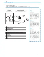
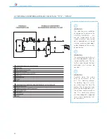
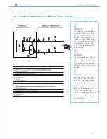
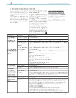
7. ELECTRICAL POWER SUPPLY CONNECTIONS
1. Before making the electrical con-
nections ensure that the isolator
is open.
2. Open the front control panel.
3. Use the holes provided in the
lower part of the cabinet for the
electrical power supply and for
other external wiring connections.
4. Enter cables into the control panel
only through the apertures provided.
5. Avoid direct contact with un-insula-
ted copper tubes and compressors.
6. Identify the terminals for electrical
connection with reference to the
wiring diagram provided loose
with the unit.
7. Take the power cable into the
control panel and connect to ter-
minals U-N and PE with respect
to (U) phase, (N) neutral, (PE)
earth in the case of single phase
units (230V/50Hz),
8. U-V-W for phases, N for neu-
tral and PE for earth in the
case of three phase units
(400V/3N/50Hz).
9. Replace the inspection panels.
10. Ensure that all protection removed
for the electrical connection are re-
placed before powering the unit.
11. Place the main isolator (external
to the unit) to “ON”.


