background image

TC3006

(LED/ELED/LASER)

User's Manual

Rev. 1.8

-7-

Chapter 2 - Installation

Unpacking the Unit

Before unpacking any equipment, inspect all shipping containers for evidence of external damage caused
during transportation. The equipment should also be inspected for damage after it is removed from the
container(s). Claims concerning shipping damage should be made directly to the pertinent shipping agencies.
Any discrepancies should be reported immediately to the Customer Service Department at TC Communi-
cations, Inc.

Equipment Location

The TC3006 should be located in an area that provides adequate light,  work space, and ventilation.  Avoid
locating it next to any equipment that may produce electrical interference or strong magnetic fields, such as
elevator shafts or heavy duty power supplies.  As with any electronic equipment, keep the unit from excessive
moisture, heat, vibration, and freezing temperatures.

Power Supply

Standard input power to the TC3006 is 12VDC @600mA. There are two pairs of terminal block connectors
on the rear panel (labeled "PWR A" and "PWR B").  Only one pair is required to power the unit. Polarity
is indicated on each connector block. If both pairs are connected, the built-in power redundancy feature will
be utilized.  When this feature is utilized, both "A" and "B" share the load.  If one power source fails, the other
will assume the full load.  Polarity is indicated on each connector block. Alternate power sources are available
as an option (see Chapter 4 - Specifications).

Dry Contact Relay Alarm

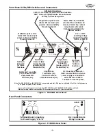
A terminal block connector on the rear panel (labeled
"ALARM") provides for the dry contact relay alarm (see Figure
2).  Normally in the OPEN position, the loss of either optic signal
will trigger an alarm condition and force the switch to the
CLOSED position.  This relay can be used in conjunction with
an external device to monitor the condition of the fiber optic
links.  Note: If SW4 (DISALM) on the front panel is in the
Down position, the audio buzzer will not sound and the dry
contact relay will not activate.

Dry Contact Relay

Alarm Switch

To remote alarm status indicator

Max switch voltage: 100VDC

Switch current: 0.5Amp
Max carry current: 1.2Amp
Contact resistance: 0.2Ohm

Reply switch specifications

Содержание TC3006

Страница 1: ... to any specifica tion TC Communications Inc reserves the right to change or modify the contents of this manual at any time without prior notification TC3006 GIGABIT ETHERNET FIBER OPTIC MODE CONVERTER User s Manual COPYRIGHT 1992 2009 ALL RIGHTS RESERVED MODEL S N DATE TC Communications Inc 17881 Cartwright Road Irvine CA 92614 Tel 949 852 1972 Fax 949 852 1948 Web Site www tccomm com Email info ...

Страница 2: ...n Distances typical 4 Launch Power Sensitivity 4 Front Panel LEDs DIP Switches and Connectors 6 Rear Panel Connectors 6 Chapter 2 Installation 7 Unpacking the Unit 7 Equipment Location 7 Power Supply 7 Dry Contact Alarm Relay 7 Installation Diagrams 8 Chapter 3 Troubleshooting 9 Chapter 4 Specifications 10 Appendix A 11 Return Policy 11 Warranty 11 ...

Страница 3: ... extending transmission distances and or enabling dissimilar fiber optic devices to be used with different fiber types The optic receiver detects the incoming optical signal and regenerates it for transmission through the second optic transmitter The TC3006 is available in multiple configurations depending on your communication requirements When both sides have the same wavelength the TC3006 works...

Страница 4: ...ch Power 6 0 dBm 1310nm Receiver PIN Diode typical Sensitivity 16 0 dBm 1310nm Optic saturation level 0 dBm 1310nm Loss Budget Multimode 50 or 62 5 125µm 1310nm 10 dB Distance Multimode 50 or 62 5 125µm 1310nm up to 2km distance Wavelength Multimode 1310nm Connector ST FC SC Single Mode 1310nm 20km Option Transmitter FP Laser typical Launch Power 10 dBm 1310nm Receiver PIN Diode typical Sensitivit...

Страница 5: ...el 9dBm 1550nm Loss Budget Single Mode 9 125µm 1550nm 32dB Distance Single Mode 9 125µm 1550nm up to 120km distance Wavelength Single Mode 1550nm LASER Connector ST FC SC Single One Fiber 40km Model Transmitter Typical Launch Power 3 to 2 dBm 1310nm 1550nm 9 125µm Receiver PIN Diode typical Sensitivity 23 dBm 1310nm 1550nm 9 125µm Optic saturation level 3 dBm Loss Budget 1310nm 1550nm Single Mode ...

Страница 6: ...ed for future functions Not Used Reserved for future functions Single Mode Receiver Rx Connect to remote unit s SM Transmitter Tx Multimode Receiver Rx Connect to local equipment s MM Transmitter Tx Multimode optic receive status MM received optic power is above sensitivity threshold when lit Single Mode optic receive status SM received optic power is above sensitivity threshold when lit Alarm Whe...

Страница 7: ...ock connectors on the rear panel labeled PWR A and PWR B Only one pair is required to power the unit Polarity is indicated on each connector block If both pairs are connected the built in power redundancy feature will be utilized When this feature is utilized both A and B share the load If one power source fails the other will assume the full load Polarity is indicated on each connector block Alte...

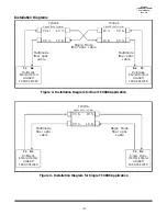
Страница 8: ...ode Converter Multimode 850nm 1300nm GIGABIT TRANSCEIVER Rx Tx MM Tx MM Rx Multimode fiber optic cable Single Mode 1300nm 1550nm GIGABIT TRANSCEIVER Tx Rx SM Tx SM Rx Single Mode fiber optic cable TC3006 Gigabit Mode Converter Multimode 850nm 1300nm GIGABIT TRANSCEIVER Rx Tx MM Tx MM Rx Multimode fiber optic cable MM Rx MM Tx TC3006 Gigabit Mode Converter Multimode 850nm 1300nm GIGABIT TRANSCEIVER...

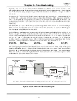
Страница 9: ...ptic in question simply disconnect the optic connector and back it out of the receptacle about 1 8 of an inch creating a gap between the fiber connector and the receiver Verify that the equipment is still in sync with the optic signal and that the overdrive condition has been corrected To resolve the overdrive condition permanently insert a 5dB or 10dB in line attenuator into the problem link In l...

Страница 10: ...DC 600mA typical Optional 24VDC 48VDC 125VDC or 115 230VAC with an external power cube Temperature Operating 10o C to 50o C Hi Temp Version Optional 20o C to 70o C Storage 40o C to 90o C Humidity 95 non condensing Physical Characteristics Rack Mountable Card Stand Alone Unit Height 7 0 17 7 cm Height 1 4 3 5 cm Width 1 2 3 1 cm Width 7 1 18 cm Depth 5 8 14 8 cm Depth 6 6 16 6 cm Weight 8 5 oz 188 ...

Страница 11: ...on may first inspect such goods at the premises of the Buyer or may give written authorization to Buyer to return the goods to TC Communications Inc transportation charges prepaid for examination by TC Communications Inc Buyer shall bear the risk of loss until all goods authorized to be returned are delivered to TC Communications Inc TC Communications Inc shall not be liable for any inspection pac...

Отзывы: