(C) TBProAudio 2018
Page 3 of 9
3 Design
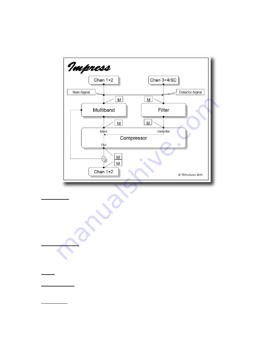
Diagram below shows the basic structure of Impress:
Compressor:
The compressor part has two inputs (Main and Detector) and one output (Out):
the main signal is the audio stream to be processed by the compressor, the detector signal is
the signal for the level detection. In most applications both signals are the same, for side-chain
effects separate signals are used.
Beside the classic "to go" design Impress offers a clean,
low aliasing
design with two
envelope follower. The gain stage could run in "vintage" mode with a thermal noise
emulation. The "knee" function is optimized for
low aliasing
operation.
Multiband Filter:
The main signal could run through a multiband filter stage. The signal is
split into three frequency bands, the mid band feeds the compressor, the output of the
compressor is mixed with the low and high band again. The multiband filter is based on the
Linkwitz-Riley
design (up to 192 dB/Oct steepness), which prevents any phase shifts.
Filter:
The detector signal could also run through a filter stage .
Detector Input:
The detector signal path could use either channel 1+2 or channel 3+4/side-
chain.
Monitoring:
Signals through Impress can be individually monitored in order to control the
effect of each signal stage (M).


