


TB Wood’s • 888-829-6637
P-5071-TBW • Form 885D
3
To Remove:
1.
Loosen and remove all of the cap screws from the idler assembly.
2. Insert the cap screws into the tapped holes in the mating hub. Evenly and progressively tighten the
cap screws until the idler bushing and mating hub separate.
3. Remove idler assembly from the mounting structure.
Replacement Parts:
Following is a list of the replacement bearings.
SH-BB
G275
SD-BB
G275
SK-BB
G276
SF-BB
G276
E-BB
G277
Bushing
Replacement
Size
Bearings
(2 per unit)
3
. Mount the assembly to the mounting structure. Place lockwasher and then outer nut on idler bushing
stud, Figure 2. Using a torque wrench, tighten the outer nut to the value listed in Table 2.
Note:
If the assembly will be threaded into a tapped hole in the mounting surface, extreme care
should be used to prevent the inner nut from turning against the bearings. Additional tightening force
on inner nut will cause bearings to fail prematurely.
WARNING
The inner nut has been tightened to 5 ft. lbs. DO NOT tamper with or retighten
above this value or the bearings will fail prematurely.
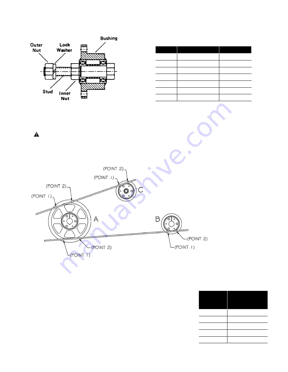
4. Make sure idler assembly is parallel with both the driveR and driveN shaft. Properly align the driveR,
driveN, and idler assembly by the four-point method illustrated in Figure 3, below.
SH-BB
1/2-13NC
60 ft. lb.
SD-BB
1/2-13NC
60 ft. lb.
SD-BB58
5/8-11NC
125 ft. lb.
SK-BB
3/4-10NC
225 ft. lb.
SF-BB
3/4-10NC
225 ft. lb.
SF-BB1
1-8NC
300 ft. lb.
E-BB
1 3/8-8NC
750 ft. lb.
Idler
Cap Screw
Torque
Table 2 – Outer Nut Tightening Torque
Note: The inner nut torque should not
exceed 5 ft. lbs. when reassembling.
Note: Straight edge must touch
two points on A and two points
on B and C.
Figure 3
Figure 2
3. Mount the assembly to the mounting structure. Place lockwasher and then outer nut on idler bushing stud,
Figure 2. Using a torque wrench, tighten the outer nut to the value listed in Table 2.
Note
: If the assembly will be threaded into a tapped hole in the mounting surface, extreme care should be
used to prevent the inner nut from turning against the bearings. Additional tightening force on inner nut will
cause bearings to fail prematurely.
WARNING: The inner nut has been tightened to 5 ft. lbs. DO NOT tamper with or retighten
above this value or the bearings will fail prematurely.
4. Make sure idler assembly is parallel with both the driveR and driveN shaft. Properly align the driveR,
driveN, and idler assembly by the four-point method illustrated in Figure 3, below.
To Remove:
1. Loosen and remove all of the cap screws from the idler assembly.
2. Insert the cap screws into the tapped holes in the mating hub. Evenly and progressively tighten the cap
screws until the idler bushing and mating hub separate.
3. Remove idler assembly from the mounting structure.
Replacement Parts:
Following is a list of the replacement bearings.
Note:
The inner nut torque should not exceed 5 ft. lbs. when reassembling.
To Remove:
1.
Loosen and remove all of the cap screws from the idler assembly.
2. Insert the cap screws into the tapped holes in the mating hub. Evenly and progressively tighten the
cap screws until the idler bushing and mating hub separate.
3. Remove idler assembly from the mounting structure.
Replacement Parts:
Following is a list of the replacement bearings.
SH-BB
G275
SD-BB
G275
SK-BB
G276
SF-BB
G276
E-BB
G277
Bushing
Replacement
Size
Bearings
(2 per unit)
3
. Mount the assembly to the mounting structure. Place lockwasher and then outer nut on idler bushing
stud, Figure 2. Using a torque wrench, tighten the outer nut to the value listed in Table 2.
Note:
If the assembly will be threaded into a tapped hole in the mounting surface, extreme care
should be used to prevent the inner nut from turning against the bearings. Additional tightening force
on inner nut will cause bearings to fail prematurely.
WARNING
The inner nut has been tightened to 5 ft. lbs. DO NOT tamper with or retighten
above this value or the bearings will fail prematurely.
4. Make sure idler assembly is parallel with both the driveR and driveN shaft. Properly align the driveR,
driveN, and idler assembly by the four-point method illustrated in Figure 3, below.
SH-BB
1/2-13NC
60 ft. lb.
SD-BB
1/2-13NC
60 ft. lb.
SD-BB58
5/8-11NC
125 ft. lb.
SK-BB
3/4-10NC
225 ft. lb.
SF-BB
3/4-10NC
225 ft. lb.
SF-BB1
1-8NC
300 ft. lb.
E-BB
1 3/8-8NC
750 ft. lb.
Idler
Cap Screw
Torque
Table 2 – Outer Nut Tightening Torque
Note: The inner nut torque should not
exceed 5 ft. lbs. when reassembling.
Note: Straight edge must touch
two points on A and two points
on B and C.
Figure 3
Figure 2
Note
: Straight edge must
touch two points on A and two
points on B and C.
Figure 3
Figure 2
Table 2
–
Outer Nut Tightening Torque
Idler
Cap Screw
Torque
SH-BB
1/2-13NC
60 ft. lb.
SD-BB
1/2-13NC
60 ft. lb.
SD-BB
58 5/8-11NC
125 ft. lb.
SK-BB
3/4-10NC
225 ft. lb.
SF-BB
3/4-10NC
225 ft. lb.
SF-BB1
1-8NC
300 ft. lb.
E-BB 1
3/8-8NC
750 ft. lb.
Bushing
Size
Replacement
Bearings
(2 per unit)
SH-BB
G275
SD-BB
G275
SK-BB
G276
SF-BB
G276
E-BB
G277


