
INSTALLATION INSTRUCTIONS (continued)
32-F238 / 32-F238SSS SINGLE SIDED INDICATOR DEADBOLT
IMPORTANT
document includes template must print at 100%
8.5 x 11”
4
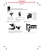
INSTALL STRIKE
Close door. Locate strike in
jamb and center line of strike.
Open door and extend line to
door stop. Measure half of door
thickness plus 1/8” from door
stop. Vertically mark centerline
for strike.
CENTER LINE
5
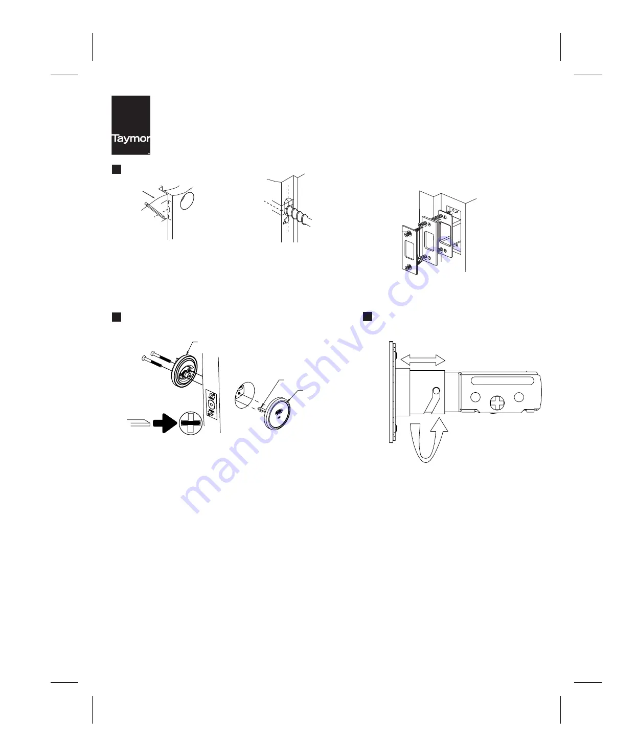
INSTALL THUMBTURN ASSEMBLY AND BLANK PLATE
Insert torque blade horizontally into deadbolt latch. Crank until indicator
assembly is flush with the door face. Mate the thumbturn assembly with the
torque blade on the indicator assembly. Insert the screws through the holes of
the thumbturn assembly and latch body. Tighten the screws to the threaded
posts of the blank mounting plate. Tighten the assembly so the complete
assembly is tight to the door.
JAMB
A.
Drill (2) 1” (25.4 mm) holes 1-1/4” (31.7 mm) deep
in door jamb, 5/16” (8 mm) above and 5/16” (8 mm)
below horizontal center line.
CAUTION:
Hole must be drilled a full 1-1/4” (31.7 mm) deep
to ensure proper functioning.
B.
Match screw holes on
strike with vertical
center lines on jamb.
Mark outline of strike
and chisel 1/4” (6.4
mm) deep for flush fit
of dust box, wood
frame reinforcer, and
strike. Place dust box
and wood frame
reinforcer into mortise
area ad tighten to the
frame using 3” wood
screws. Insert the
strike and tighten to
the frame with #8
screws.
C.
TORQUE BLADE
THUMB TURN
ASSEMBLY
INDICATOR
ASSEMBLY
6
BACKSET ADJUSTMENT
To change deadbolt to a 2-3/8” backset, rotate faceplate 1/2 turn.


