14
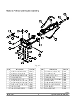
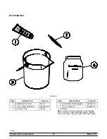
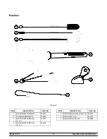
Model C713
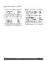
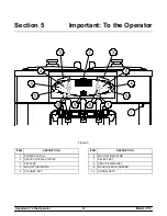
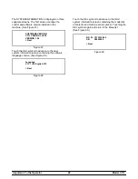
Important: To the Operator
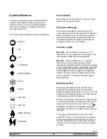
Wash Symbol
The WASH symbol
will illuminate when it is
touched. This indicates beater motor operation. The
STANDBY or AUTO modes must be cancelled first
to activate the WASH mode.
Auto Symbol
The AUTO symbol
will illuminate when it is
touched. This indicates that the refrigeration system
has been activated. In the AUTO mode, the WASH
or STANDBY functions are automatically cancelled.
Note:
An indicating light and an audible tone will
sound whenever a mode of operation has been
selected. To cancel any function, touch the key
again. The light and the mode of operation will shut
off.
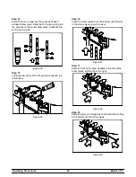
Reset Mechanism
The reset buttons are located in the back panel of
the machine. It protects the beater motor from an
overload condition. Should an overload occur, the
reset mechanism will trip. To properly reset the
freezer place the power switch in the OFF position.
Press the reset button firmly. Turn the power switch
to the ON position. Touch the WASH symbol
and
observe the freezer's performance.
WARNING: Do not use metal objects to
press the reset button.
Failure to comply may
result in severe personal injury or death.
If the beater motor is turning properly, touch the
WASH symbol
to cancel the cycle. Touch the
AUTO symbol
to resume normal operation. If the
freezer shuts down again, contact your authorized
service technician.
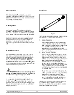
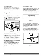
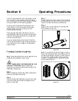
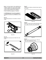
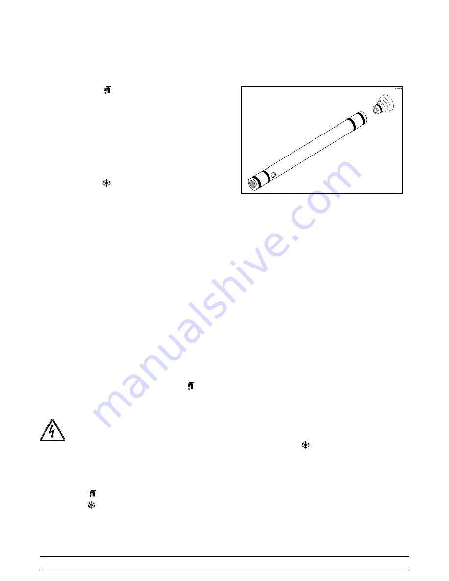
Feed Tube
Figure 6
The feed tube serves two purposes. One end of the
tube has a hole and the other end does not.
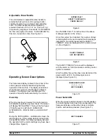
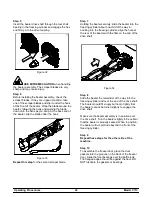
1.
Normal Operation
During normal operation, the end of the feed
tube with the hole is placed into the mix inlet
hole. Every time the draw handle is raised, new
mix and air from the hopper flow into the
freezing cylinder. This keeps the freezing
cylinder properly loaded and maintains overrun.
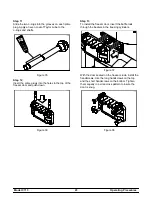
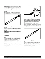
2.
Long “No Sale” Periods
During long “No Sale” periods, the unit can be
placed into the Standby mode. This maintains
product temperatures below 40°F (4.4°C) in
both the hopper and the freezing cylinder, and
helps prevent overbeating and product
breakdown. To activate STANDBY, enter the
access code for the Manager Menu (see
page 16.) Remove the air orifice. Lubricate the
o-rings located on the end of the feed tube
without the hole. Place that end of the tube into
the mix inlet hole.
(
Note:
To resume normal operation, press the
AUTO symbol
. When the unit cycles off, the
product in the freezing cylinder will be at
serving viscosity. At this time, turn the feed
over. Place the end of the tube with the hole
into the mix inlet hole. Install the air orifice.)
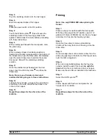
The air orifice is used to meter a certain amount of
air into the freezing cylinder. The air orifice
maintains overrun and allows enough mix to enter
the freezing cylinder after a draw.
Содержание c713
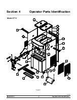
Страница 11: ...7 Model C713 Operator Parts Identification 111115 Section 4 Operator Parts Identification Model C713 Figure 1 ...
Страница 49: ...Model C713 059899 27 7 25 11 ...
Страница 50: ...Model C713 059899 33 7 25 11 ...
Страница 51: ...Model C713 059899 40 7 25 11 ...
Страница 52: ...Model C713 059899 58 7 25 11 ...


