Taylex ABS1500 Скачать руководство пользователя страница 3

Page 2 of 16 

1.

INTRODUCTION

The Taylex ABS1500 Sewage Treatment System is designed to be installed both in-ground and
above 

ground

, collecting all wastewater from a domestic residence. This manual has been put

together to explain the installation process of the ABS1500 system as a guide only. Some sites may
differ in access and slope which need to be taken into account when delivering and installing the
system.

2.

SAFETY INSTRUCTIONS

Follow all safety instruction provided by the onsite builder and ensure 
you have all the relevant licences to perform this work. 

Ensure the correct measurements are in place to prevent the 
general public from entering the site during the installation of the 

ABS1500

. Excavated holes should be fenced if the 

ABS1500

 is not 

immediately installed. 

SLIPPERY WHEN WET! 
During cleaning, maintenance & repair work, the surrounding area may 
become extremely slippery due to spilt water. Caution is to be taken 
when walking/standing near the 

ABS1500

 when these activities are 

being conducted. 

Use safe lifting techniques when installing/relocating the ABS

1500

Ensure that all lifting equipment is in a safe working order and the area is 
clear of obstructions. Ensure all lifting equipment used has a suitable 
capacity and current testing/compliance. 

The waste water contained in the 

ABS1500

 may contain harmful 

bacteria. Persons coming in contact with wastewater must immediately 
wash and disinfect all exposed areas. Contact your personal physician for 
all health concerns.  

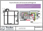
WARNING - To reduce the risk of electrical shock, all works requiring 
access to the blower box MUST be carried out by a licenced electrician or 
Taylex Accredited Service Agent (TASA) prior to final commissioning. 

Содержание ABS1500

Страница 1: ...INSTALLATION MANUAL CONCRETE ADVANCED BLOWER SYSTEM 1500 ABS1500 ...

Страница 2: ...Tall 300 Excavation Instructions 10 d ABS1500 Tall 300 Lifting Instructions 11 e ABS1500 Tall 400 Excavation Instructions 12 f ABS1500 Tall 400 Lifting Instructions 13 g ABS1500 Tall 600 Excavation Instructions 14 h ABS1500 Tall 600 Lifting Instructions 15 11 ELECTRICAL CONNECTION DIAGRAM 16 Note Do not act solely on the basis of the material contained in this document Items herein are general com...

Страница 3: ...0 is not immediately installed SLIPPERY WHEN WET During cleaning maintenance repair work the surrounding area may become extremely slippery due to spilt water Caution is to be taken when walking standing near the ABS1500 when these activities are being conducted Use safe lifting techniques when installing relocating the ABS1500 Ensure that all lifting equipment is in a safe working order and the a...

Страница 4: ... for heavy equipment access Weather conditions 5 MARK OUT To ensure the ABS1500 is installed in the position nominated by the Home Owner Builder the location of the ABS1500 should be marked out prior to excavation The installer at this stage should have a copy of the approved site plans showing the location of the ABS1500 as well as the required local authority approval If not it is advised to del...

Страница 5: ...ehind the vehicle before placing it into the prepared hole Maximum reach from the rear of the truck to the centre of ABS1500 will vary depending on the size of the crane To enable the ABS1500 to be unloaded a minimum width of 7m may vary depending on crane truck will be required at the hole This distance allows for the width of the crane truck the width of the tank itself and clearance for safe an...

Страница 6: ...Page 5 of 16 ...

Страница 7: ...r and surface waters away from the system The ABS1500 comes with 4 different heights to accommodate invert levels as deep as 1270mm below ground level Width Height Inlet Height from bottom of tank Inlet Depth from ground level Required Base 5 7mm Drainage Gravel Sand Hole Width Hole Depth ABS1500 STD 2425 2300 1530 670 100 3000 2300 ABS1500 Tall 300 2425 2600 1530 970 100 3000 2600 ABS1500 Tall 40...

Страница 8: ... and clog the system and irrigation pump Ensure that the backfill material is kept at least 100mm below the surface of the systems lid Evenly fill the system with approximately 5 000L of water through the centre Aeration Chamber to prevent movement through the ground as the water pressure enters the system Organise drainage contractors to connect to the system The drainage connection is a standard...

Страница 9: ...mm drainage gravel or sand 4 Ensure bottom of hole is level 5 Backfill with soil from Excavation in no more than 500mm equally distributed layers around the tank Avoid backfilling with rocks over 300mm 6 To prevent flotation fill the ABS with 5 000lt of water immediately through hole above the aeration chamber see diagram below 7 Ensure top of gravel sand is 1530mm to bottom of inlet ELECTRICIAN Conne...

Страница 10: ... Inlet 1530 mm 1 Always use a Spreader Bar and ensure it is certified 2 Lower chains through TOP lifting holes provided in the lid of the ABS 3 Loop chains through the lifting holes directly below on the inside wall of the ABS 4 Steel reinforcing bars have been installed inside the concrete for lifting purposes Only lift this tank from these holes 5 If you don t use a Spreader Bar you risk damaging...

Страница 11: ...over 300mm 6 To prevent flotation fill the ABS with 5 000lt of water immediately through hole above the aeration chamber see diagram below 7 Ensure top of gravel sand is 1530mm to bottom of inlet 100mm of 5mm 7mm drainage gravel or sand Please Note 5 000lt of water to be placed in this chamber to prevent flotation Top of tank to be a minimum of 100mm above landscaped ground level Lifting Holes 100mm ...

Страница 12: ... the ABS 3 Loop chains through the lifting holes directly below on the inside wall of the ABS 4 Steel reinforcing bars have been installed inside the concrete for lifting purposes Only lift this tank from these holes 5 If you don t use a Spreader Bar you risk damaging the ABS 6 Ensure the tank is empty before lifting REACH OF CRANE CRANE TRUCK To be determined by your crane crane truck operator Li...

Страница 13: ... over 300mm 6 To prevent flotation fill the ABS with 5 000lt of water immediately through hole above the aeration chamber see diagram below 7 Ensure top of gravel sand is 1530mm to bottom of inlet 100mm of 5mm 7mm drainage gravel or sand Please Note 5 000lt of water to be placed in this chamber to prevent flotation Top of tank to be a minimum of 100mm above landscaped ground level Lifting Holes 100mm...

Страница 14: ... the ABS 3 Loop chains through the lifting holes directly below on the inside wall of the ABS 4 Steel reinforcing bars have been installed inside the concrete for lifting purposes Only lift this tank from these holes 5 If you don t use a Spreader Bar you risk damaging the ABS 6 Ensure the tank is empty before lifting USE ONLY CERTIFIED LIFTING BARS REACH OF CRANE CRANE TRUCK To be determined by yo...

Страница 15: ... over 300mm 6 To prevent flotation fill the ABS with 5 000lt of water immediately through hole above the aeration chamber see diagram below 7 Ensure top of gravel sand is 1530mm to bottom of inlet 100mm of 5mm 7mm drainage gravel or sand Please Note 5 000lt of water to be placed in this chamber to prevent flotation Top of tank to be a minimum of 100mm above landscaped ground level Lifting Holes 100mm...

Страница 16: ...d in the lid of the ABS 3 Loop chains through the lifting holes directly below on the inside wall of the ABS 4 Steel reinforcing bars have been installed inside the concrete for lifting purposes Only lift this tank from these holes 5 If you don t use a Spreader Bar you risk damaging the ABS 6 Ensure the tank is empty before lifting USE ONLY CERTIFIED LIFTING BARS REACH OF CRANE CRANE TRUCK To be d...

Страница 17: ...re Hole of Isolator Switch Electrician Connect the incoming mains with the existing wires that connect to the double GPO ensuring the correct polarity is maintained Weather Proof Single GPO IMPORTANT INSTRUCTIONS Dedicated 10amp Circuit Breaker in power board Taylex Best Practise Hardwired with 2 5mm wire ANE Active Neutral Earth to Weatherproof GPO located in blower box Connect the 12V to 240V po...

Отзывы: