background image


FCC INFORMATION 


This equipment has been tested and found to comply with the limits for a class B digital 

device, pursuant to Part 15 of the FCC Rules. These limits are designed to provide   

reasonable protection against harmful interference in a residential installation. This 

equipment generates, uses and can radiate radio frequency energy and, if not installed and   

used in accordance with the instructions, may cause harmful interference to radio   

communications. 

However, there is no guarantee that interference will not occur in a particular installation.   

If his equipment does cause harmful interference to radio or television reception, which can   

be determined by turning the equipment off and on, the user is encouraged to try to correct 

the interference by one or more of the following measures: 

- Reorient or relocate the receiving antenna. 

- Increase the separation between the equipment and receiver. 

- Connect the equipment into an outlet on a circuit different from that to which the receiver   

is connected. 

- Consult the dealer or an experienced radio/TV technician for help. 

Shielded interface cables and A.C. power cord, if any, must be used in order to comply   

with emission limits. 

Changes or modifications not expressly approved by the party responsible for compliance 

could void the user's authority to operate the equipment. 


SAFETY PRECAUTIONS 


1. Operate this unit only from the type of power source indicated on the label. 

2. Do not block or cover ventilation openings on the back or bottom of the monitor cabinet. 

3. Do not place this monitor near a radiator or heating vent. 

4. Do not push objects of any kind through cabinet openings. This may result in fire or   

electrical shock. 

5.  Before adding attachments always ask a service technician to perform routine safety 

tests to determine that equipment is in safe operating condition. Ground potential tests 

should be part of the routine safety check made by the service technician. 

6. Do not place monitor on an unstable cart, stand, or shelf where it may fall and injure   

personnel or damage equipment. 

Содержание TCM-0902

Страница 1: ...Operating Instructions For Color Video Monitor TCM 0902 TCM 1001 TCM 1002S TCM 1402S TCM 1501 TCM 1701 TCM 1901 TCM 2102S TATUNG Company Of America...

Страница 2: ......

Страница 3: ...d Rear Views 6 6 TCM 1002S Monitor Front and Rear Views 7 7 TCM 1402S Monitor Front and Rear Views 8 8 TSCM 1501 HI RES Monitor Front and Rear Views 9 9 TCM 1701 HI RES Monitor Front and Rear Views 10...

Страница 4: ...into an outlet on a circuit different from that to which the receiver is connected Consult the dealer or an experienced radio TV technician for help Shielded interface cables and A C power cord if an...

Страница 5: ...plug the unit immediately and notify the service technician A If liquid has been spilled into the display or the display has been exposed to rain or water B If the unit has been dropped or the cabinet...

Страница 6: ...s 50 Hz 3 Video Input Signal CVBS1 CVBS2 S Y C 4 Audio Input Signal AU1 AU2 5 Input Power 100 240V AC 6 Limited twelve months warranty STANDARD SYSTEM COMPONENTS AND ATTACHMENTS The various components...

Страница 7: ...Color Adjustment 7 Sharpness Adjustment 8 Volume Adjustment 9 CVBS1 CVBS2 S Y C Select Switch TCM 0902 Rear View 1 Power Inlet 2 Video 1 Input BNC Connector 3 Video 1 Output BNC Connector 4 Video 2 I...

Страница 8: ...TCM 1001 Rear View 1 Power Inlet 2 Video 1 Video 2 Select Switch 3 Video Load Impedance Switch 4 Video 1 Input BNC Connector 5 Video 1 Output BNC Connector 6 Video 2 Input BNC Connector 7 Video 2 Out...

Страница 9: ...t 6 Color Adjustment 7 Sharpness Adjustment 8 Volume Adjustment 9 CVBS1 S Y C Select Switch TCM 1002S Rear View 1 Power Inlet 2 Video Load Impedance Switch 3 Video 1 Input BNC Connector 4 Video 1 Outp...

Страница 10: ...t 6 Color Adjustment 7 Sharpness Adjustment 8 Volume Adjustment 9 CVBS1 S Y C Select Switch TCM 1402S Rear View 1 Power Inlet 2 Video Load Impedance Switch 3 Video 1 Input BNC Connector 4 Video 1 Outp...

Страница 11: ...ch 10 Audio 1 Audio 2 Select Switch TCM 1501 Rear View 1 Power Inlet 2 Video 1 Load Impedance Switch 3 Video 2 Load Impedance Switch 4 Video 1 Input BNC Connector 5 Video 1 Output BNC Connector 6 Vide...

Страница 12: ...tch 10 Audio 1 Audio 2 Select Switch TCM 1701 Rear View 1 Power Inlet 2 Video 1 Load Impedance Switch 3 Video 2 Load Impedance Switch 4 Video 1 Input BNC Connector 5 Video 1 Output BNC Connector 6 Vid...

Страница 13: ...tch 10 Audio 1 Audio 2 Select Switch TCM 1901 Rear View 1 Power Inlet 2 Video 1 Load Impedance Switch 3 Video 2 Load Impedance Switch 4 Video 1 Input BNC Connector 5 Video 1 Output BNC Connector 6 Vid...

Страница 14: ...ect Switch 11 Underscan Select Switch 12 16 9 Select Switch TCM 2102S Rear View 1 Power Inlet 2 Video 1 Load Impedance Switch 3 Video 2 Load Impedance Switch 4 Video 1 Input BNC Connector 5 Video 1 Ou...

Страница 15: ...o video in RCA BNC connectors of the monitor 5 Turn your device system power switch ON then turn the monitor power switch ON The power indicator will be ON at this moment 6 Allow about 30 seconds for...

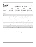
Страница 16: ...n 300 lines Y C more than 350 lines 300 lines Y C more than 350 lines 350 lines Y C more than 450 lines 400 lines Y C more than 450 lines Sweep Linearity 10 GENERAL Input Output Video S Video 2 BNC in...

Страница 17: ...gh output 2 BNC inputs 75ohms or Hi Z 2 looping through outputs 1 input DIN 1 loop through output 2 BNC inputs 75ohms or Hi Z 2 looping through outputs 1 input DIN 1 loop through output 2 BNC inputs 7...

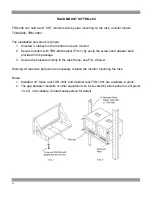
Страница 18: ...racket FIG 1 by using the screws and adapter bars provided in the package 3 Secure the brackets directly to the rack frame see FIG 2 below Warning At least two persons are necessary to place the monit...

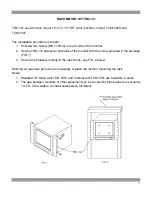
Страница 19: ...side of the monitor with the screw provided in the package FIG 1 3 Secure the brackets directly to the rack frame see FIG 2 below Warning At least two persons are necessary to place the monitor mount...

Страница 20: ...re mounting brackets to both side of the monitor with original screws FIG 1 3 Secure the brackets directly to the rack frame see FIG 2 below Warning At least two persons are necessary to mount the mon...

Страница 21: ...TATUNG COMPANY OF AMERICA 2850 EL PRESIDIO ST LONG BEACH CA90810 800 827 2850 3121 0266 09...

Отзывы: