background image

GTS

Technical Manual

5. March 2013

Edition: V1.10/2013

5-33

Copyright © 2013, Diversey Inc.

05

.4

0.1

5 s

qu

eeg

ee -

 fro

nt b

la

de ol

d set

 u

- 4

55

B_4

55E_

755B e

co_

755E_

75

5B p

ower_

85

5B p

ower_

V1.1

0.f

m

5.6

Squeegee

5.6.4

Mounting of front blade old setup

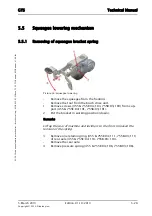
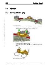
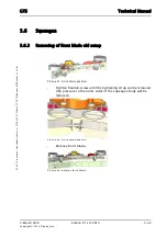
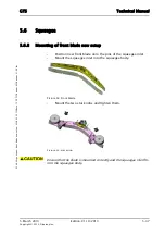
Position new front blade.

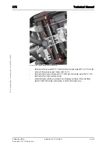
Picture 44: Front blade position

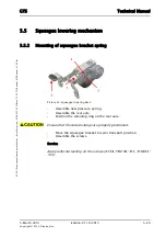
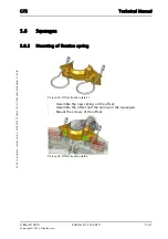
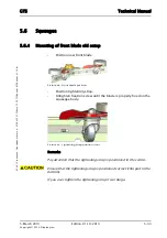
Position tightening strap.

Untighten fixation screw until the blade is properly fixed on the 

squeegee body.

Picture 45: Tightening strap position front

Remarks

Pay attention that the tightening strap is positioned in the centre.

Ensure that the tightening strap is positioned correct (thin part to the 

bottom).

If you over tighten the tightening strap it can bulge.

Содержание swingo 455B

Страница 1: ...Edition V1 10 2013 Technical Manual...

Страница 2: ...ange 1 4 2 Technical information 2 4 2 1 Machine profile 2 4 2 2 Technical data 2 4 2 3 Dimensions and weights 3 4 3 Battery 4 4 3 1 Battery compartment 4 4 3 2 Battery specifications 4 4 4 Charger 5...

Страница 3: ...e old setup 34 5 6 5 Removing of back blade old setup 35 5 6 6 Mounting of back blade old setup 36 5 6 7 Removing of front blade new setup 37 5 6 8 Mounting of front blade new setup 38 5 6 9 Removing...

Страница 4: ...nting of electronics 10 6 3 3 Electronic connections 11 6 4 Charger 14 6 4 1 Removing of charger 14 6 4 2 Mounting of charger 15 6 4 3 Charger connections 16 6 5 Schematics 18 6 5 1 Battery connection...

Страница 5: ...5 March 2013 Edition V1 10 2013 Copyright 2013 Diversey Inc Technical Manual 1 Forward...

Страница 6: ...technical training 1 2 Technical Training The Technical Training is addressed as reference book for the technical training sessions and will be distributed to the floor care responsible and or to the...

Страница 7: ...oaded from e spares documents 1 4 Summary We are convinced that the Technical Manual concept together with the Technical Training are powerful tools which will help our service organisations to achiev...

Страница 8: ...5 March 2013 Edition V1 10 2013 Copyright 2013 Diversey Inc Technical Manual 2 Elementary...

Страница 9: ...at are used in this machine please carefully read the product label and Ma terial Safety Data Sheet MSDS Empty water tanks prior to carrying out any maintenance Ensure contaminated water is emptied in...

Страница 10: ...ents Almost any material can generate static electricity The ability to store or unload the charge depends on the type of material Static discharge can damage devices this can result in immediate prod...

Страница 11: ...5 March 2013 Edition V1 10 2013 Copyright 2013 Diversey Inc Technical Manual 3 General...

Страница 12: ...he original place If you have to remove self locking nuts you should replace them by new ones 3 1 3 Direction description On the RH always means on the right hand side of the machine in working direct...

Страница 13: ...Diversey Inc 03 1 swingo general_V1 00 fm 3 2 Required material 3 2 1 Tools A standard range of tools is required e g Fork spanners Allen keys Torx keys 3 2 2 Material No special tools are required T...

Страница 14: ...5 March 2013 Edition V1 10 2013 Copyright 2013 Diversey Inc Technical Manual 4 Technical data...

Страница 15: ...iption Version Series 7518366 swingo 455 B 01 7518367 swingo 455 B BMS EURO 01 7518368 swingo 455 B BMS UK 01 7518369 swingo 455 B BMS SEV 01 7518370 swingo 455 B BMS DK 01 7518371 swingo 455 B BMS NA...

Страница 16: ...h 1290 Working width mm 430 Squeegee width mm 690 Solution tank l 22 Recovery tank l 25 Table 2 Machine profile Pos Unit Value Noise level ECO mode dB A 68 63 Vibration m s2 0 5 Approvals CE Nominal c...

Страница 17: ...1100 480 920 Door pass through with without squeegee mm 690 489 Battery compartment L W H mm 350 319 200 Net weight without batteries empty tank kg 58 Weight ready to use with 50 Ah batteries kg 120 W...

Страница 18: ...compartment 4 3 2 Battery specifications Please use batteries from Exide Sonnenschein as this is our preferred partner BMS is only for dry gel batteries Dry batteries Pos Unit Value Battery compartmen...

Страница 19: ...system Pos Unit Value Primary V 230 240 Primary Hz 50 60 Secondary V 24 Secondary A 9 Protection type IP30 Approval UL CE Cable length BMS cable m 3 Table 7 Charger Pos Unit Value Brush system mm 430...

Страница 20: ...essories Additional parts 4 7 1 Accessories Pos Value Vacuum motor W 400 Max air flow l s 24 Max vacuum mbar 93 Max vacuum kPa 9 3 Table 9 Suction power SKU Article 8504750 Scrubbing brush standard 43...

Страница 21: ...5 March 2013 Edition V1 10 2013 Copyright 2013 Diversey Inc Technical Manual 5 Mechanical...

Страница 22: ...ndle to the front side so you can access the screws Remove the screw 01 106 for the cover 01 105 for USB access Remove the cover for USB access Remove the 12 screws 01 107 and the 4 screws 01 117 into...

Страница 23: ...5 2 Copyright 2013 Diversey Inc 05 10 11 handle cover and electronic 455B_V1 00 fm Disconnect ribbon cable of dashboard before moving the electronics Lift the lever of the ribbon cable connector to r...

Страница 24: ...cture 3 Handle without cover and electronics Connect the ribbon cable to the electronics Position the electronics Ensure that the loop of the ribbon cable is positioned correctly and does not touch th...

Страница 25: ...Edition V1 10 2013 5 4 Copyright 2013 Diversey Inc 05 10 11 handle cover and electronic 455B_V1 00 fm Tighten the handle cover with the 12 screws and 4 screws into electronics Position the cover for U...

Страница 26: ...1 3 Removing of switch lever Picture 5 Switch lever Remove handle cover according to chapter REMOVING OF HANDLE COVER AND ELECTRONICS Remove screw 01 102 for left switch lever and screw 01 102 for ri...

Страница 27: ...sure that the RH switch lever has the bolt with magnet 01 118 mounted Adjustment Ensure that the gear teeth of the switch levers are correctly positioned The switch levers have to be horizontally in o...

Страница 28: ...lever 455B_V1 00 fm 5 1 Handle 5 1 5 Removing of handle adjustment lever Picture 7 Handle adjustment lever Remove handle cover according to chapter REMOVING OF HANDLE COVER AND ELECTRONICS Remove the...

Страница 29: ...ent lever 455B_V1 00 fm 5 1 Handle 5 1 6 Mounting of handle adjustment lever Picture 8 Handle adjustment lever Mount the handle adjustment lever onto handle Mount the eccentric shaft together with the...

Страница 30: ...le at the lever Remove handle cover according to chapter REMOVING OF HANDLE COVER AND ELECTRONICS Remove the eccentric shaft together with the end bolt of the bowden cable according to chapter REMOVIN...

Страница 31: ...01 144 Remove the two sustaining discs 01 147 from the articulation Remove the toothed wheel 01 151 Remove one of the retaining washer 01 137 from the axle Remove the axle 01 142 Picture 11 Articulati...

Страница 32: ...GTS Technical Manual 5 March 2013 Edition V1 10 2013 5 11 Copyright 2013 Diversey Inc 05 10 24 handle toothrocker 455B_V1 00 fm Picture 12 Toothrocker detail...

Страница 33: ...1 8 Mounting of toothrocker Picture 13 Toothrocker detail Mount the two toothrockers onto the axle of the bowden cable Remarks The two toothrockers are different in shape The mounting position doesn t...

Страница 34: ...axle Service Lubricate the toothrockers with grease 07 131 Mount the eccentric shaft together with the end bolt of the bowden cable according to chapter MOUNTING OF HANDLE ADJUSTMENT LEVER Position t...

Страница 35: ...1 00 fm Picture 15 Sustaining disc Mount the articulation onto the tank Position the two cover discs Mount the 6 screws Mount the handle cover according to chapter MOUNTING OF HANDLE COVER AND ELECTRO...

Страница 36: ...emove handle cover according to chapter REMOVING OF HANDLE COVER AND ELECTRONICS Remove the toothrockers according to chapter REMOVING OF TOOTHROCKER Remove the castor 01 135 from the handle housing R...

Страница 37: ...he articulation Mount the toothrockers according to chapter MOUNTING OF TOOTHROCKER Mount the eccentric shaft together with the end bolt of the bowden cable according to chapter MOUNTING OF HANDLE ADJ...

Страница 38: ...n cable 01 119 on the lever 01 116 Remarks By turning the eccentric shaft counter clockwise you tension the bowden cable Picture 20 Eccentric shaft detail Adjustment Make sure that the bowden cable is...

Страница 39: ...move handle cover according to chapter REMOVING OF HANDLE COVER AND ELECTRONICS Remove the toothrockers according to chapter REMOVING OF TOOTHROCKER Remove the bowden cable according to chapter REMOVI...

Страница 40: ...nting of articulation Picture 22 Articulation Mount the guide bar Mount the articulation Mount the screw from the handle housing Mount the bowden cable according to chapter MOUNTING OF BOWDEN CABLE Mo...

Страница 41: ...101 Remove the tank cover and the recovery tank 02 105 Loosen the hose clamp 03 118 from the water regulation set 03 122 Remove the hose from the water regulation set Remove the 5 screws 02 124 from t...

Страница 42: ...E_V1 00 fm Picture 24 Clear water tank fixation Remove the screw 07 110 from the metal rope 07 127 on the side of the clear water tank 02 117 Remove the two screws 02 119 from the tank axle 02 118 Rem...

Страница 43: ...ount the two screws from the tank axle Mount the screw from the metal rope on the side of the clear water tank Close the clear water tank Mount the screws from the tank brackets Click in the cable cov...

Страница 44: ...onnect the two flexible hoses 02 106 132 from the tank cover 02 101 Picture 27 Vacuum unit detail Remove the 5 screws 02 124 from the cover vacuum unit 03 103 Unclip the cable cover 03 102 from the co...

Страница 45: ...it detail Mount the insulation and sealing parts of the vacuum motor Position the vacuum unit onto the cover and mount the 3 screws Connect the cable on the connection bloc Click in the cable cover Po...

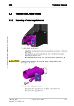
Страница 46: ...re 29 Water regulation set Untighten the fresh water and draining hose clamp 03 118 and 02 129 Remove fresh water draining hose 02 107 from the water regulation set 03 122 Remove fresh water hose 03 1...

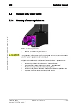
Страница 47: ...t new water regulation set The diameter of the water outlet on the tank shrinks as soon the outlet stub or water regulation set is removed Replace the outlet stub immediately with the water regulation...

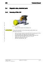
Страница 48: ...lter 24V Picture 32 Filter 24V Remove filter set 09 102 of filter 24V Ensure that no water is in the fresh water system before you disconnect the hoses Remove the two fixation screws 09 103 from chass...

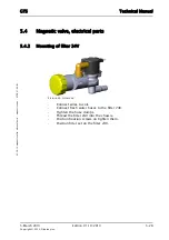
Страница 49: ...magnetic valve 455B_V1 00 fm 5 4 Magnetic valve electrical parts 5 4 2 Mounting of filter 24V Picture 33 Filter 24V Connect wires to coil Connect fresh water hoses to the filter 24V Tighten the hose...

Страница 50: ...owering Remove the squeegee from the fixation Remove the tool from the brush drive unit 1 Remove screws 455 755E 04 103 755B 03 103 from sup port 455 755E 04 101 755B 03 101 2 Put the bracket in worki...

Страница 51: ...eegee lowering mechanism 5 5 2 Mounting of squeegee bracket spring Picture 35 Squeegee lowering back Assemble new pressure spring Assemble the rear axle Position the retaining ring on the rear axle En...

Страница 52: ...r_855B power_V1 00 fm 5 6 Squeegee 5 6 1 Removing of fixation spring Picture 36 Squeegee Unscrew the 2 screws 455 755E 05 112 755B 04 112 of the offset fixation 455 755E 05 113 755B 04 113 Picture 37...

Страница 53: ...xation spring 455B_455E_755B eco_755E_755B power_855B power_V1 00 fm 5 6 Squeegee 5 6 2 Mounting of fixation spring Picture 39 Offset fixation detail 1 Assemble the new spring on the offset Assemble t...

Страница 54: ...eco_755E_755B power_855B power_V1 10 fm 5 6 Squeegee 5 6 3 Removing of front blade old setup Picture 41 Front blade position Tighten fixation screw until the tightening strap can be removed the press...

Страница 55: ...old setup Position new front blade Picture 44 Front blade position Position tightening strap Untighten fixation screw until the blade is properly fixed on the squeegee body Picture 45 Tightening strap...

Страница 56: ...5B eco_755E_755B power_855B power_V1 10 fm 5 6 Squeegee 5 6 5 Removing of back blade old setup Picture 46 Back blade position Untighten the fixation screws 455 755E 05 111 755B 04 111 on both sides to...

Страница 57: ...p Position new back blade Picture 49 Back blade position Position tightening strap Tighten fixation screws until the blade is properly fixed on the squeegee body Picture 50 Tightening strap position b...

Страница 58: ..._855B power_V1 00 fm 5 6 Squeegee 5 6 7 Removing of front blade new setup Picture 51 Squeegee new setup Remove the two star knobs 455 755E 05 108 755B 855 04 108 Press out the squeegee inlet 455 755E...

Страница 59: ...855B power_V1 00 fm 5 6 Squeegee 5 6 8 Mounting of front blade new setup Position new front blade onto the pins of the squeegee inlet Mount the squeegee inlet into the squeegee body Picture 54 Front b...

Страница 60: ...power_V1 00 fm 5 6 Squeegee 5 6 9 Removing of back blade new setup Picture 56 Squeegee new setup Remove the two star knobs 455 755E 05 108 755B 855 04 108 Press out the squeegee inlet 455 755E 05 124...

Страница 61: ..._855B power_V1 00 fm 5 6 Squeegee 5 6 10 Mounting of back blade new setup Position new back blade onto the pins of the squeegee inlet Mount the squeegee inlet into the squeegee body Picture 59 Back bl...

Страница 62: ...partment on the LH side by removing the screw 455 02 122 755B 09 114 755E 09 110 from the locking system Lay the machine on the LH side Unlock battery compartment on the RH side by removing the screw...

Страница 63: ...g to e spares Tighten the fixation screw with a 19 mm fork spanner Lock battery compartment on the RH side with the screw of the locking system Lift up the machine Lock battery compartment on the LH s...

Страница 64: ...microswitch Unscrew microswitch fixation screw 455B 06 117 755B 07 117 Remove microswitch 455B 06 123 755B 07 123 Remove wheel 455B 07 142 755B 06 109 on RH side Remove retaining ring 455B 06 107 755B...

Страница 65: ...d in new foot lever Position washer and nuts then tighten them Position cradle and foot lever in the correct position Assemble axle Assemble microswitch and adjust accordingly Adjustment The foot leve...

Страница 66: ...ush drive unit Disconnect the fresh water hose from the brush drive unit Disconnect the brush motor wires from the connection block Remove self locking nuts 455B 06 124 755B 07 124 on the LH and RH si...

Страница 67: ...on the cradles Position the bolt and the eccentric shaft Position the eccentric disc Adjustment Default setting refer to spare parts catalogue Eccentric disc 455B 06 120 755B 07 120 Position 4 Eccent...

Страница 68: ...eccentric shaft Tighten all self locking nuts Do not use the locking lever 455B 06 116 755B 07 116 to tighten the eccentric shaft 455B 06 110 755B 07 110 Connect the brush motor to the connection bloc...

Страница 69: ...3 Removing of brush belt New setup Picture 73 Brush drive Remove brush drive unit according to chapter REMOVING OF BRUSH DRIVE UNIT Position brush drive unit upside down Remove the three screws 08 13...

Страница 70: ...e tensioning roller on the brush base plate Position the fixation screw and tighten it only as much as required to move over the brush base plate nozzle Move the tensioning roller with a 17 mm fork sp...

Страница 71: ...ording to chapter REMOVING OF BRUSH BELT NEW SETUP Remove the three screws 08 136 of the coupling 08 135 Remove the coupling from brush drive pulley 08 127 Remove the catch 08 131 Remove the centre pl...

Страница 72: ...ling ring 08 147 Mount the new pulley Position the retaining ring Picture 79 Brush drive pulley detail retaining ring Service Apply lubricant 08 149 on the sealing ring 08 130 Position the sealing rin...

Страница 73: ...or belt Picture 80 Brush drive Remove brush drive unit according to chapter REMOVING OF BRUSH DRIVE UNIT Remove brush belt according to chapter REMOVING OF BRUSH BELT NEW SETUP OLD SETUP Remove brush...

Страница 74: ...new motor new belt Take care that the belt is positioned correctly Insert the counter head screw Position the two other screws Service Apply adhesive looking 09 138 on the screws 09 134 Tension the b...

Страница 75: ...5 March 2013 Edition V1 10 2013 Copyright 2013 Diversey Inc Technical Manual 6 Electrical...

Страница 76: ...e foil keyboard visualises the states of the machine It also functions as a connection between the power electronics and the devices e g vacuum motor and pump Applying the correct torque where require...

Страница 77: ...with power The power electronics get power and it enables the proc essor to start and go into the self holding The power electronics stays on as long as It is not switched OFF by the ON OFF button Th...

Страница 78: ...0 fm 6 2 Dashboard 6 2 1 Removing of dashboard Picture 1 Dashboard Remove handle cover according to chapter REMOVING OF HANDLE COVER AND ELECTRONICS in the mechanical section Remove the dashboard foil...

Страница 79: ...board 6 2 2 Mounting of dashboard Picture 2 Dashboard Clean the surface where the dashboard will be placed Position the new dashboard foil Complete assembling according to the chapter REMOVING OF HAND...

Страница 80: ...TS Technical Manual 5 March 2013 Edition V1 10 2013 6 5 Copyright 2013 Diversey Inc 06 14 31 dashboard connections 455B_V1 00 fm 6 2 Dashboard 6 2 3 Dashboard connections Picture 3 Dashboard connectio...

Страница 81: ...en 7 7 8 Dosing ON OFF 8 Dosing ON OFF 9 Dosing ON OFF 9 Dosing ON OFF LED green 10 Status battery 10 Battery status LED green 11 Status battery 11 Battery status LED green 12 Status battery 12 Batter...

Страница 82: ...2013 Edition V1 10 2013 6 7 Copyright 2013 Diversey Inc 06 14 31 dashboard connections 455B_V1 00 fm 1 LED with two colours LED green and red Pos Plug Description plug Pin Description pin Table 1 Das...

Страница 83: ...nter To reset the service hour counter LED you have to perform the following steps Picture 4 Dashboard foil service LED reset Press the buttons ON OFF and Eco together The machine will switch ON Ensur...

Страница 84: ...Inc 06 18 11 electronics 455B_V1 00 fm 6 3 Electronics 6 3 1 Removing of electronics Picture 5 Electronics Remove handle cover according to chapter REMOVING OF HANDLE COVER AND ELECTRONICS in the mec...

Страница 85: ...3 2 Mounting of electronics Picture 6 Electronics Connect the wires to the electronics Complete assembling according to the chapter MOUNTING OF HANDLE COVER AND ELECTRONICS Tighten the connectors wit...

Страница 86: ...echnical Manual 5 March 2013 Edition V1 10 2013 6 11 Copyright 2013 Diversey Inc 06 18 21 electronics connections 455B_V1 00 fm 6 3 Electronics 6 3 3 Electronic connections Picture 7 Electronic connec...

Страница 87: ...pump 1 Not used 6 1 Charger communication 1 Charge yellow 6 1 Charger communication 2 Charged green 6 1 Charger communication 3 Failure red 6 1 Charger communication 4 Immobiliser 6 1 Charger communi...

Страница 88: ...connections 455B_V1 00 fm A Hall sensor Brush start B Hall sensor Wiping blade 350 C Label software Firmware version Boot version D Label of electronics Name of machine Hardware version Production num...

Страница 89: ...cture 8 Charger Remove the screws 455B 02 122 755B 09 114 for the battery compartment Open the battery compartment Remove connector from the charger Disconnect battery connection and thread out wires...

Страница 90: ...00 fm 6 4 Charger 6 4 2 Mounting of charger Picture 9 Charger Position charger and mount the screws Thread in main cord and connect it to the connection block Thread in battery wires and connect accor...

Страница 91: ...Manual 5 March 2013 Edition V1 10 2013 6 16 Copyright 2013 Diversey Inc 06 20 21 charger connections 455B_755B eco_755B power 855B power_V1 00 fm 6 4 Charger 6 4 3 Charger connections Picture 10 Charg...

Страница 92: ...inus 2 S3 Power main cord 1 Phase 2 S3 Power main cord 2 Neutral 2 S3 Power main cord 3 GND 3 X7 Charger communication 1 Not connected 3 X7 Charger communication 2 Not connected 3 X7 Charger communica...

Страница 93: ...5 March 2013 Edition V1 10 2013 6 18 Copyright 2013 Diversey Inc 06 28 11 schematics battery connection 455B_755B eco_755B power_855B power_V1 00 fm 6 5 Schematics 6 5 1 Battery connection Picture 11...

Страница 94: ...nical Manual 5 March 2013 Edition V1 10 2013 6 19 Copyright 2013 Diversey Inc 06 28 22 schematics electrical schematics 455B_V1 00 fm 6 5 Schematics 6 5 2 Electrical schematics Picture 12 Electrical s...

Страница 95: ...5 March 2013 Edition V1 10 2013 Copyright 2013 Diversey Inc Technical Manual 7 Additional information...

Страница 96: ...012 TASKI swingo 450 455 750 755 760 Drive Optional wheels avaliable for E and Eco models Q2 12 2012 08 21 02 20120 TASKI swingo 455 755 760 855 Brush drive Belt comes off on battery driven machines 1...

Страница 97: ...ngo 455B Squeegee New squeegee 3935 2012 30 17 12 2012 TASKI swingo 350 455 755 760 855 1255 1260 1650 1850 XP 4000 5000 Service Tool Service Tool Update Version 6 04 2013 01 13 02 2013 TASKI swingo 3...

Страница 98: ...5 March 2013 Edition V1 10 2013 Copyright 2013 Diversey Inc Technical Manual 8 Revision...

Страница 99: ...07 2012 All All New structure 1 00 25 07 2012 Additional in formation GTS Newsletter Instruction Added GTS Newsletter Instruction 1 00 26 07 2013 Electrical System architecture Updated pictures 1 10 2...

Страница 100: ...5 March 2013 Edition V1 10 2013 Copyright 2013 Diversey Inc Technical Manual 9 Appendix...

Страница 101: ...ies 3 1 D Dashboard 6 3 6 4 6 5 6 8 Dashboard connections 6 5 Dashboard connector description 6 6 Dimensions and weights 4 3 Direction description 3 1 Dry batteries 4 4 E Electrical schematics 6 19 El...

Страница 102: ...spring 5 29 5 30 Squeegee lowering mechanism 5 29 5 30 Start up Self holding 6 2 Static discharge 2 2 Suction power 4 6 Summary 1 2 Switch lever 5 5 System architecture 6 1 System overview 6 1 T Tank...

Страница 103: ...5 March 2013 Edition V1 10 2013 Copyright 2013 Diversey Inc Technical Manual 10 Notes...

Отзывы: