background image

©Copyright Task Force Tips, Inc. 1999-2017 

LIZ-010 December 26, 2017 Rev12

17

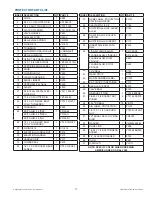
PROTECTOR PARTS LIST

INDEX DESCRIPTION

QTY PART #

1

SLIDE

1

Z285

2

5/32 X 1-1/2 COTTER PIN

1

VP156X1.5

3

3/4-10 SLOT FIN HEX NUT

1

VT75-10SF

4

FLAT SS WASHER

1

VW1.5X81-134

5

VALVE HANDLE

1

Z280

6

SMALLEY RING

1

V4235

7

BELLEVILLE SPRING

1

VM4900

8

O-RING-214

1

VO-214

9

TRUNNION

1

Z265

10

AUTOMATIC DRAIN VALVE

1

A-DRAIN-KIT

11

BELL ALUMINUM

1

Z210A

12

1/4"NPT HEX HEAD PLUG

1

VFHP2M

13

1/4 X 1-3/8 HDP SPIROL

1

VP250X1.375H

14

OVERRIDE KNOB LABEL

1

Y4176

15

KNOB

1

Z245

16

LOCKING BOLT

1

Z240

17

CLAMP THREADED

2

Z221

18

SWIVEL INSERT

4

Z225

19

UPPER SWIVEL SEAL

1

Z230

20

CLAMP

2

Z220

21

5/16-18 ALL METAL FLEX-
LOCK NUT 

1

VT31-18SLNT

22

1/16 X 1/2 COTTER PIN

1

VP063X.50

23

1/2-13 X 1-3/4 HEX BOLT 
FULLY THREADED

1

VT50-13HX1.7

24

TRUNNION

1

Z260

25

EXIT ALUM. 2.5"BSP

1

Z310ABJ

EXIT ALUM. 2.5"NPSH

Z310AIJ

EXIT ALUM. 2.5"NH

Z310ANJ

26

1/2-13 X 2-3/4 HEX BOLT 
FULLY THREADED

1

VT50-13HX2.7

27

O-RING-016

1

VO-016

28

ELEVATION HANDLE NUT

1

Z316

29

ELEVATION HANDLE

1

Z315

30

HANDLE GRIP

1

Z317

31

LOWER SEAL

1

Z275

32

1/2-13 X 2.5 SOCKET HEAD 
SCREW 

1

VT50-13SH2.5

INDEX DESCRIPTION

QTY PART #

33

NAME LABEL: PROTECTOR 
STATION MONITOR

1

ZL101

34

CLEVIS PIN 1/4 X 2 

1

X180

35

ROTATIONAL LOCK LEVER 
ALUM.

1

X160

36

ROTATION LOCK LEVER 
SPRING

1

X152

37

ROTATION LOCK INSERT

1

X170

38

INDUSTRIAL BELL WITH 
RIM 

1

Z425

39

3"ANSI FLANGE ALUM.

1

X410-3ASA

FLANGE ALUM. 4"ANSI/XF

X414-4ASA

FLANGE ALUM. DN80 
PN16/XF

X423

FLANGE ALUM. DN100 
PN16/XF

X424

40

CUP SEAL

1

X125

41

WEAR STRIP

1

X120

42

MODEL NUMBER LABEL

1

A1303

43

SS CLEVIS PIN RETAINER

1

X137

44

REAR VALVE SEAT

1

Z270

45

VALVE BALL

1

Z250

46

GREASE FITTING

1

VT25-28ZERK

47

3/8-24 X 3/8 SOCKET SET 
SCREW

2

VT37-24SS375

48

5/16" SS BALL 

76

VB.312

49

S/N LABEL: PROTECTOR/

1

ZL102

50

1/2-13 X 1-1/4 COUPLING 
NUT

1

VT50-13CPLNT

51

EXTERNAL SELF-LOCKING 
RING

1

VR4290

52

WASHER

1

VW500x265-63

53

SLIDE LINK

1

Z286

54

1/4-28 X 1/2 BUTTON HEAD 
SCREW

1

VT25-28BH500

55

2.5" CLAPPER WASHER

1

X752

56

PLUG

1

Z261

57

O-RING-117

1

VO-117

NOTE: SPECIFY COLOR WHEN ORDERING

AMERICAN RED OR RAL 3000

Содержание PROTECTOR

Страница 1: ...n at www tft com serial number This instruction manual is intended to familiarize firefighters and maintenance personnel with the operation servicing and safety procedures associated with the PROTECTOR Station Monitor This manual should be kept available to all operating and maintenance personnel TASK FORCE TIPS INC MADE IN USA www tft com 3701 Innovation Way Valparaiso IN 46383 9327 USA 800 348 268...

Страница 2: ...ipment you may be called upon to use 3 It is your responsibility to know that you have been properly trained in Firefighting and or Emergency Response and in the use precautions and care of any equipment you may be called upon to use 4 It is your responsibility to be in proper physical condition and to maintain the personal skill level required to operate any equipment you may be called upon to use...

Страница 3: ... 4 4 HANDLE INSTALLATION 4 5 DRAINING RESIDUAL WATER 5 0 OPERATION 9 5 1 VALVE OPERATION 5 2 HORIZONTAL ROTATION CONTROL 5 3 ELEVATION CONTROL 6 0 FLOW CHARACTERISTICS 10 6 1 AUTOMATIC NOZZLES 6 2 STACKED TIPS FLOW AND REACH 6 3 STREAM STRAIGHTENERS 6 3 1 STREAM STRAIGHTENERS WITH STACKED TIPS 6 3 2 STREAM STRAIGHTENERS WITH FOG NOZZLES 6 4 MONITOR FRICTION LOSS 7 0 DRAWINGS AND PART LISTS 16 8 0 ...

Страница 4: ...abuse exposure to severe chemicals Deformed or cracked flanges damaged as a result of improper installation Excessive bolt torque Wrong tightening sequence WARNING Injury can result from an inadequately supported monitor The monitor mount must be capable of supporting 1050 lbs 475 kg of nozzle reaction force WARNING The stream exiting a monitor is very powerful and capable of causing injury and pro...

Страница 5: ...ed within a few minutes with common hand tools All models are equipped with an automatic drain valve to fully evacuate the monitor and optional on off valve after each use A threaded pipe port 1 4 NPT 6mm is provided for pressure gauge installation Maximum pressure is 250 psi 17 bar The Protector is hard anodized ANSI 356 T6 aluminum and is fully powder coat finished inside and out Swivel clamps 3 7...

Страница 6: ... 225 250 275 300 0 250 500 750 1000 1250 1500 Flow Rate l min Monitor Inlet Pressure bar Monitor Inlet Pressure psi Flow Rate gpm Protector Safe Operating Envelope Nozzle B Nozzle D Nozzle A Nozzle C Do not exceed Maximum Monitor Inlet Pressure Do not exceed Max Monitor Flow Rate Nozzle A flows 500 gpm at 100 psi 1900 l min at 7 bar K factor 50 Nozzle B flows 750 gpm at 100 psi 2800 l min at 7 bar K...

Страница 7: ... cm 16 2 in 41 1 cm 19 1 in 48 5 cm 19 1 in 48 5 cm Height at 30 elevation 24 7 in 62 7 cm 24 7 in 62 7 cm 27 6 in 70 1 cm 27 6 in 70 1 cm Max height at 80 elevation 31 0 in 78 7 cm 31 0 in 78 7 cm 33 9 in 86 1 cm 33 9 in 86 1 cm Fig 3 4 Monitor height with each inlet flange option 3 5 OUTLET OPTIONS Three options are available for the 2 5 inch male threaded outlet National Hose Thread NH also refe...

Страница 8: ...ce FLANGE TYPE OUTSIDE DIAMETER THICKNESS BOLT HOLE CIRCLE OF BOLTS SIZE OF BOLTS TORQUE ON BOLTS in mm in mm in mm in mm ft lb N m 3 ANSI 125 150 DN80 PN20 7 5 190 0 75 20 6 0 152 5 4 5 8 16 76 80 100 110 4 ANSI 150 DN100 PN20 9 0 230 0 94 23 7 5 190 8 5 8 16 76 80 100 110 DN80 PN16 FLANGE 7 9 200 0 87 22 6 3 160 8 5 8 16 76 80 100 110 DN100 PN16 FLANGE 8 7 220 0 87 22 7 1 180 8 5 8 16 76 80 100 ...

Страница 9: ...inage port must be opened underground below the frost depth to keep water out of the standpipe until the next use All Protector station monitors are equipped with an automatic drain valve attached to a port located just above the valve seat and or lower seal The automatic drain valve ensures the monitor is completely drained following use which minimizes susceptibility to damage from corrosion and...

Страница 10: ...ically on the direction control handle see figure 5 2 Twisting the elevation locking knob clockwise will increase the drag on the upper swivel joint to lock the monitor at a particular elevation Select discharge devices that do not exceed the 70 ft lb locking capability of the elevation lock For a typical fog nozzle the maximum allowable weight works out to be about 40 lbs 18 1 kg CAUTION Injury ca...

Страница 11: ... BAR NOZZLE DIAMETER MM 2 8 4 1 5 5 7 FLOW l min REACTION KG FLOW l min REACTION KG FLOW l min REACTION KG FLOW l min REACTION KG 35 1360 50 1670 80 1890 110 2120 140 38 1590 60 1970 100 2270 130 2540 160 45 2200 90 2650 130 3070 170 3440 220 50 2840 110 3480 170 4010 230 4500 290 Fig 6 2A Stacked Tip Flow Table 0 0 0 2 1 2 1 0 0 8 0 6 0 4 PRESSURE BAR 0 20 40 60 80 100 120 140 160 180 200 0 200 4...

Страница 12: ...ET VERTICAL DISTANCE FEET VERTICAL DISTANCE M 0 0 4 0 0 80 0 0 0 6 0 0 2 HORIZONTAL DISTANCE M 1 50 INCH TIP 0 10 20 0 20 40 60 80 0 0 40 0 80 0 120 0 160 0 200 0 240 0 280 0 40 PSI 60 PSI 100 PSI 80 PSI HORIZONTAL DISTANCE FEET VERTICAL DISTANCE FEET VERTICAL DISTANCE M 0 0 4 0 0 80 0 0 0 6 0 0 2 HORIZONTAL DISTANCE M 1 75 INCH TIP 0 10 20 0 20 40 60 80 0 0 40 0 80 0 120 0 160 0 200 0 240 0 280 0...

Страница 13: ... DISTANCE METERS VERTICAL DISTANCE METERS 2 0 INCH TIP 100 PSI 1190 GPM 60 DEGREES 30 DEGREES 45 DEGREES 75 DEGREES Fig 6 2D Effects of Elevation on Trajectory 0 10 40 20 80 0 40 80 120 160 200 240 280 320 360 HORIZONTAL DISTANCE FEET 2 00 INCH TIP 100 PSI 1190 GPM VERTICAL DISTANCE FEET NO WIND 20 MPH TAILWIND 20 MPH HEADWIND 0 0 1 5 7 0 5 5 2 0 VERTICAL DISTANCE M HORIZONTAL DISTANCE M Fig 6 2E E...

Страница 14: ... straightener on the TFT stacked tip nozzle OK 6 3 2 STREAM STRAIGHTENERS WITH FOG NOZZLES When using a fog nozzle it is recommended that no stream straightener be used since the fog nozzle s flow path generally serves as a stream straightener Use of a stream straightener with a fog nozzle will increase the stresses on the elevation locking clamp due to the greater cantilevered weight Select discha...

Страница 15: ... 25 30 0 200 400 600 800 1000 1200 FLOW GPM FRICTION LOSS PSI 2 1 psi 350 gpm 0 1 bar 1300 l min 4 4 psi 500 gpm 0 3 bar 2000 l min 9 9 psi 750 gpm 0 7 bar 3000 l min 27 psi 1250 gpm 1 8 bar 4500 l min FRICTION LOSS BAR FLOW l min 1 2 0 0 750 1525 2300 3030 3800 4500 Fig 6 4 Protector Station Monitor Friction Loss ...

Страница 16: ...17 LIZ 010 December 26 2017 Rev12 16 7 0 DRAWING PART LIST 56 8 55 54 1 2 3 4 5 6 7 8 9 11 12 17 13 16 15 18 53 52 51 50 20 18 49 48 47 46 43 42 41 40 44 45 39 38 37 36 35 34 33 32 17 18 31 30 29 28 27 26 25 24 23 22 21 20 18 19 11 10 14 57 ...

Страница 17: ...1 VT50 13HX2 7 27 O RING 016 1 VO 016 28 ELEVATION HANDLE NUT 1 Z316 29 ELEVATION HANDLE 1 Z315 30 HANDLE GRIP 1 Z317 31 LOWER SEAL 1 Z275 32 1 2 13 X 2 5 SOCKET HEAD SCREW 1 VT50 13SH2 5 INDEX DESCRIPTION QTY PART 33 NAME LABEL PROTECTOR STATION MONITOR 1 ZL101 34 CLEVIS PIN 1 4 X 2 1 X180 35 ROTATIONAL LOCK LEVER ALUM 1 X160 36 ROTATION LOCK LEVER SPRING 1 X152 37 ROTATION LOCK INSERT 1 X170 38 ...

Страница 18: ... discharge of its obligations under this limited warranty If TFT makes this election claimant shall return the equipment to TFT free and clear of any liens and encumbrances This is a limited warranty The original purchaser of the equipment any person to whom it is transferred and any person who is an intended or unintended beneficiary of the equipment shall not be entitled to recover from TFT any c...

Страница 19: ... Remove coupling nut from lower clamp using 5 8 wrench or socket Remove socket head cap screw from lower clamp using 3 8 male hex wrench Separate the joint by pivoting the clamp piece off of the flanged section Pull out the valve seat and lower seal Clean away dirt on flanges and clamps Inspect seal and sealing surfaces of valve seat and flange Replace damaged parts as needed Apply grease to surface o...

Страница 20: ...structions There is no damage to any thread or other connection All locks and hold down devices work properly The pressure setting on the relief valve if so equipped is set correctly Gaskets are in good repair There is no obvious damage such as missing broken or loose parts There is no damage to the appliance that could impair operation e g dents cracks or other defects All swiveling elements rota...

Отзывы: