5
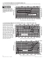
2.3 HYDRAULIC INSTALLATION
2.5 PATTERN CONTROL
2.6 USE WITH FOAM
2.4 ELECTRIC INSTALLATION
On nozzles with hydraulic stream shaper actuation, the hydraulic system is connected to the nozzle with two 1/8"-27 NPT (1/4”-18 NPT
on Masterstream 4000) female ports on the filter block located on the nozzle's stream shaper. When the port on the left of the filter block
(as seen from behind the nozzle) is pressurized, the shaper moves back into the wide fog position. Pressurizing the right port moves
the shaper forward into straight stream. Hydraulic lines must be flexible to allow for movement of the stream shaper.
Use only clean fluid compatible with Buna N Compound (Nitrile). System must be free from all dirt, chips and contaminants.
Replacement filter elements are available from TFT (item #M160). Maximum hydraulic pressure is 1000 psi (70 bar, 7000 Kpa) for
Masterstream 1250 or Masterstream 2000 Nozzles. (1500 psi, 105 bar, 10500 Kpa for Masterstream 4000 Nozzle).
TFT's Masterstream Series nozzles have full pattern control from straight stream to wide fog. On models with manual shapers, turning
the stream shaper clockwise (as seen from the operating position behind the nozzle) moves the shaper to the straight stream position.
Turning the stream shaper counterclockwise will result in an increasingly wider pattern.
Since the stream trim point varies with flow, the nozzle should be "trimmed" after changing the flow to obtain the straightest and farthest
reaching stream. To properly trim a stream, first open the pattern to narrow fog. Then close the stream to parallel to give maximum
reach. Note: Turning the shaper further forward will cause stream crossover and reduce the effective reach of the nozzle.
The Masterstream Series nozzles may be used with foam solutions. Refer to fire service training for the proper use of foam.
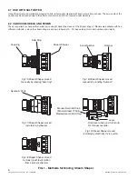
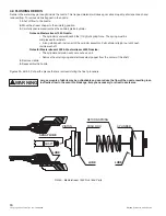
Nozzles with electric stream shaper actuation are shipped with a wiring diagram (TFT item #LIM-040). Other documentation is
available on request. The actuator is not rated as ignition proof, explosion proof, or intrinsically safe. NOTE: Masterstream 1250 and
Masterstream 2000 nozzles are equipped with manual override in case of electrical power failure. Refer to figure 1D for manual
override instructions.
For Class B fires, lack of foam or interruption in the foam stream can cause a break in the foam
blanket and greatly increase the risk of injury or death.
Avoid using wrong type of foam on a fire, i.e. Class A foam on a Class B fire; Plunging foam into pools of burning liquid fuels; Causing
environmental damage; Directing stream at personnel.
There is a wide variety of foam concentrates. Each user is responsible for verifying that any foam
concentrate chosen to be used with this unit has been tested to assure that the foam obtained is
suitable for the purpose intended.
The electric motor and other components are ignition sources. The electric stream shaper should
be operated only in areas where there is adequate ventilation and no hazard of flammable vapor
buildup.
WARNING
WARNING
WARNING
WARNING
©Copyright Task Force Tips, Inc. 1999-2005
Assure that application rate is sufficient (see NFPA 11 or foam manufacturer's recommendations); Enough concentrate is on hand to
complete task (see NFPA for minimum duration time requirements); Foam logistics have been carefully planned.
Allow for such things as storage of foam in a location not exposed to the hazard it protects; Personnel, equipment and technique to
deliver foam at a rapid enough rate; Removal of empty foam containers; Clear path to deliver foam, as hoses and other equipment and
vehicles are deployed.
Improper use of foam can result in injury or damage to the environment. Follow foam
manufacturer's instructions and fire service training.
2.6.1 FOAMJET LX WITH MASTERSTREAM 1250 NOZZLE
3.0 AUTOMATIC NOZZLE OPERATION
To increase the expansion ratio, Task Force Tips "Foamjet LX" (model FJ-LX-M) may be used with the Masterstream 1250 nozzle. This
low expansion foam tube attaches and detaches quickly from the nozzle. Adjust nozzle spray pattern to give best foam quality. Note:
As expansion ratio is increased, the reach of the nozzle will be decreased due to the greater amount of bubbles in the stream and their
inability to penetrate the air. Generally the reach with foam is approximately 10% less than with water only. Actual results will vary based
on brand of foam, hardness of water, temperature, etc.
Automatic nozzles operate by sensing the pressure at the nozzle's inlet and adjusting the discharge opening to maintain a constant
pressure throughout the flow range of the nozzle. For example, when the pressure at the inlet increases, the exit area is automatically
increased until the inlet pressure returns to the nominal pressure of the nozzle.
Note: Inlet pressure of a Masterstream Series nozzle will stabilize at the nominal pressure (within 5%). This stabilization may take as
long as half a minute after a change in inlet pressure.
LIM-030 October 12, 2005 Rev 05


