background image

TASCAM DA-6400/DA-6400dp

 45

8 – Mark and Locate Functions

Mark functions

Adding marks

Marks can be added in the following ways.
Including the marks added by the automatic mark function, one 

take can have up to 99 marks added to it.


8

Adding marks manually

Press the 

MULTI JOG

 dial to add a mark at the current playback/

recording point.
The mark will be named “MARK xx”.


8

Adding marks automatically

The automatic mark function allows the unit to add marks 

automatically during recording. For details about the automatic 

mark function, see “Adding marks automatically when recording” 

on page 27.
The marks will be named according to type.

Reason mark added automatically Mark name

Overload indicator lit

OVERxx

Synchronization with master clock 

lost

UNLKxx

At set time interval

TIMExx

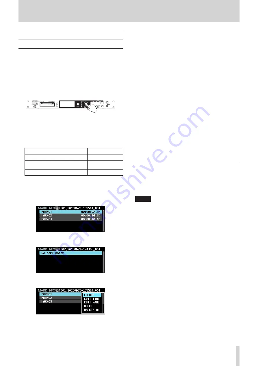
Using marks

Press the 

INFO

 button while pressing and holding the 

SHIFT


button to open the 

MARK INFO

 page.

No Mark Point

 is shown when the current take has no 

marks.

Select the desired mark on the 

MARK INFO

 Screen and press 

the 

MULTI JOG

 dial to open the mark pop-up menu.

Turn the 

MULTI JOG

 dial to select the desired item, and press 

the 

MULTI JOG

 dial to execute it as follows.


8

LOCATE

Move to the selected mark. (See “Moving to marks” on page 

45.)


8

EDIT TIME

Open the 

EDIT MARK TIME

 screen where you can edit the 

selected mark.


8

EDIT NAME

Open the 

MARK NAME

 screen where you can edit the 

name of


selected mark.


8

DELETE

Delete the selected mark. (See “Deleting marks” on page 46.)


8

DELETE ALL

Delete all marks in the current take. (See “Deleting all marks in 

the current take” on page 46.)


8

SORT BY TIME

Show marks sorted by time.


8

SORT BY NAME

Show marks sorted by name.


8

INFO

Open a pop-up with the number of marks of each type in the 

current take. (See “Viewing mark information” on page 46.)


8

CANCEL

Close the mark menu.

Moving to marks


8

Using buttons to move to marks

Press the 

.

 [MARK 

.

]

 or 

/

 [MARK 

/

]

 button while 

pressing and holding the 

SHIFT

 button to move to the previous 

or next mark.

NOTE

If the settings of the 

INPUT AUX1

INPUT AUX6

 items 

are MARK SKIP +, MARK SKIP -, TAKE/MARK SKIP +, TAKE/

MARK SKIP - or MARK on the 

PARALLEL INPUT

 screen, 

if a mark movement event is input through the PARALLEL 

connector, the transport will move one mark backward 

or forward for each event.(See “PARALLEL INPUT page 

settings” on page 38.)


8

Using the menu to move to marks

1.  Turn the 

MULTI JOG

 dial to select the mark to which you 

want to move.

2.  Press

 the 

MULTI JOG

 dial to open the mark pop-up menu, 

select the 

LOCATE

 item and press the 

MULTI JOG

 dial to 

move to the selected mark.

Содержание DA-6400

Страница 1: ...D01249320A DA 6400 DA 6400dp Digital Multitrack Recorder OWNER S MANUAL...

Страница 2: ...rence to radio communications Operation of this equipment in a residential area is like ly to cause harmful interference in which case the user will be required to correct the interference at his own...

Страница 3: ...the feet of the unit before mounting CAUTION Leave 1U of space above the unit for ventilation Allow at least 10 cm 4 in at the rear of the unit for venti lation 1 Read these instructions 2 Keep these...

Страница 4: ...ccumulators should be disposed of separately from the municipal waste stream via designated collection facilities appointed by the government or the local authorities b By disposing of waste batteries...

Страница 5: ...nnel settings 24 Setting the record function for specific channels 24 Setting the recording file format 25 Setting the file name format 26 Editing text 26 Automatically incrementing take numbers 27 In...

Страница 6: ...quirements 49 Connecting an SSD HDD to a computer 49 Disconnecting from a computer 50 11 Other Settings Information Screens and Keyboard Operations 51 INFO button and indicator appearance 51 Checking...

Страница 7: ...arranty 1 Conventions used in this manual In this manual we use the following conventions When we refer to buttons connectors and other parts of this unit we use a bold font like this MENU button When...

Страница 8: ...ther chemical agents Doing so could damage the surface or cause discolor ation Notes about SSD and HDD drives Notes about media This unit can use SSDs and HDDs for recording and playback An SSD that h...

Страница 9: ...ing the SHIFT button to open the MARK INFO screen See Using marks on page 45 6 HOME METER button o o Press when the Home Screen is open to change the time display mode o o When a Menu Screen is open p...

Страница 10: ...ith a mini plug Use the PHONES knob to adjust the headphone output level CAUTION Before connecting headphones minimize the volume with the PHONES knob Failure to do so might cause sudden loud noises w...

Страница 11: ...on while pressing and holding the MARK button to move to the next mark and resume the previous state Rear panel 8 8 DA 6400 rear panel 8 8 DA 6400dp rear panel s SLOT 2 Use this slot to install an I O...

Страница 12: ...t The following example is of a connection that controls recording and playback of this unit by level using fader starts and stops and FADER REC commands START STOP PARALLEL STOP Pin 8 GND Pin 6 REC N...

Страница 13: ...s shown relative to the length of the take Lengthens from the left end toward the right end NOTE During recording a progress bar appears to extend from the left end to the right end about every 10 sec...

Страница 14: ...level page 23 INPUT MONITOR Set input monitoring function page 23 REC FILE FORMAT page REC FUNCTION Make recording channel settings page 24 BIT LENGTH Set the bit length page 25 REC Fs Set the samplin...

Страница 15: ...he time offset from Coordi nated Universal Time UTC DST SETUP Set the daylight savings time function MEDIA page QUICK FORMAT Quickly format media page 19 FULL FORMAT Format media completely MEDIA INFO...

Страница 16: ...ss the MULTI JOG dial 8 8 Going back one step in a menu Press the EXIT PEAK CLEAR button 8 8 Returning directly to the Home Screen from a menu Press the HOME METER button Menu operation procedures In...

Страница 17: ...removing it once and reinserting it You can insert a case even when the unit is on Removing an SSD HDD case SSD HDD cases can be ejected CAUTION Do not remove the SSD HDD case from the unit when the S...

Страница 18: ...screws to secure the I O card in place 4 Turn the unit on and check the VERSION INFOR MATION screen to confirm that it has recognized the inserted I O card See Checking the firmware version on page 5...

Страница 19: ...dial to adjust the brightness of the color display and the indicators While pressing and holding the HOME METER button press and turn the MULTI JOG dial to adjust the brightness of only the color dis...

Страница 20: ...result in other trouble Setting headphones monitoring mode The headphones monitoring mode can be set 1 Select the PHONES MONITOR MODE item on the PREFERENCES page to open the PHONES MONITOR MODE scree...

Страница 21: ...switch Adjusting the brightness of the color display and various indicators EXTERNAL CONTROL This locks external control from the RS 422 and PARALLEL connectors as well as file transfer and remote co...

Страница 22: ...unit s internal clock is used WORD Synchronize with the word clock signal input through the WORD VIDEO IN connector VIDEO Synchronize with the video clock signal input through the WORD VIDEO IN conne...

Страница 23: ...ut and output headroom difference between the maximum and reference levels 1 Select the REFERENCE LEVEL item on the GENERAL page to open the REFERENCE LEVEL screen See Menu operation procedures on pag...

Страница 24: ...nnel where the cursor is NOTE You can also turn the MULTI JOG dial to select a channel Turn the MULTI JOG dial while pressing and holding the SHIFT button to move the cursor by 4 channels at a time Ma...

Страница 25: ...ORMAT page to open the BIT LENGTH screen See Menu operation procedures on page 16 2 Set the quantization bit depth Options 16bit 24bit default 3 Confirm the setting and return to the REC FILE FORMAT p...

Страница 26: ...Deleting a character Turn the MULTI JOG dial to select DEL to delete a character to the right of the cursor or BS to delete a character to the left of the cursor and press the MULTI JOG dial 8 8 Dele...

Страница 27: ...is pressed repeatedly in a short amount of time o o When the media has very little remaining open space o o When the limit to the number of files in a folder is reached Adding marks automatically when...

Страница 28: ...ures on page 16 2 Set the pause mode function Options SPLIT default Create a new file whenever recording is paused NO SPLIT Do not create a new file whenever recording is paused 3 Confirm the setting...

Страница 29: ...the signal sending and receiving devices NOTE The signal from the IF MA64 EX MADI COAXIAL IN connector is output through its MADI COAXIAL THRU connector whether the unit is on or off When the unit is...

Страница 30: ...file is selected press the HOME METER button to return to the Home Screen When a take is selected press the 7 button to return to the Home Screen and play that take When a take is selected press the 9...

Страница 31: ...ed take or file If the selected file is a take information is shown on two pages as follows Press the MULTI JOG dial to switch between the two pages Page Contents 1st Creation date and time Sampling f...

Страница 32: ...file pop up menu 2 Select the COPY item and press the MULTI JOG dial to open the copy destination folder selection screen 3 Move to the copy destination folder o o If it is the first time copying the...

Страница 33: ...dial to open the pop up file menu 2 Select the EDIT TC item in the file menu and press the MULTI JOG dial The EDIT TAKE TC screen opens 3 Use the MULTI JOG dial to change the time Press the MULTI JOG...

Страница 34: ...3 digit number _ 2 digit channel number wav T002_20150901 121554_001_02 wav ROOT DA Files da6400_takes bin T002_20150901 121554_001_64 wav T001_20150901 112313_001_01 wav T001_20150901 112313_001_02 w...

Страница 35: ...ing playback Press the 9 CHASE button Selecting takes This section explains how to select a take when there are multiple takes Skipping to the previous next take Use the MARK buttons to skip to the pr...

Страница 36: ...or JAM SYNC the waiting capture status indicator lights green when waiting to capture timecode When timecode is captured the indicator turns off START TIME item This shows the time when timecode resu...

Страница 37: ...or synchronizes to the input timecode REC RUN The timecode generator runs only during recording The timecode generator stops when not recording TC SYNC REC Recording starts when the unit synchro nizes...

Страница 38: ...nput of 50 msec or longer See Note about the PARALLEL connector on page 12 PARALLEL OUTPUT page settings 8 8 OUTPUT AUX1 OUTPUT AUX5 This shows the current functions set for OUTPUT AUX1 OUTPUT AUX5 of...

Страница 39: ...irm the changed settings and return to the Menu Screen NOTE Press the EXIT PEAK CLEAR button to cancel the menu operation and return to the Menu Screen 8 8 DNS SETUP This shows the setting status of t...

Страница 40: ...er and use it to set the built in clock Start Up 24h cycle Get the time from an NTP server and use it to set the built in clock when the unit starts up as well as when the time set with the UPDATE TIM...

Страница 41: ...ress the MULTI JOG dial to open the MODE screen When MODE is set to Disable When MODE is set to Enable MODE item Set whether or not to enable the daylight savings time function Options Disable default...

Страница 42: ...be interrupted 8 8 Overview of file operations using an FTP client application 1 Reading files from the unit Reading files from the unit is always possible 2 Adding new files to the unit Adding new f...

Страница 43: ...ders on the unit cannot be changed NOTE FTP transfer with USB flash drives is only possible when the unit is stopped Do not edit load folders skip or conduct other operations Remote control Telnet Rem...

Страница 44: ...at a time When the KEYBOARD item is set to LOCK on the LOCK SETUP screen a VNC viewer application can be used to view the unit s display but it cannot be used to control the unit If a NETWORK page set...

Страница 45: ...e to the selected mark See Moving to marks on page 45 8 8 EDIT TIME Open the EDIT MARK TIME screen where you can edit the selected mark 8 8 EDIT NAME Open the MARK NAME screen where you can edit the n...

Страница 46: ...nfirmation pop up message will appear Press the MULTI JOG dial again to open a second confir mation pop up message 4 Press and hold the MULTI JOG dial to delete all marks in the current take NOTE Dele...

Страница 47: ...g will be the same as it was before stopped in playback standby or playing For this reason playback will resume at the new time only after locating during playback NOTE Using the Backspace or key on t...

Страница 48: ...of a WAV file does not have a 2 digit channel number it will be recognized as a single take Preparation before loading If an SSD or HDD drive is to be used with this unit for the first time use this u...

Страница 49: ...omputer that this unit supports Computer system requirements This unit can be connected to the following types of computers 8 8 Windows Windows 10 Windows 8 including 8 1 Windows 7 8 8 Mac Mac OS X 10...

Страница 50: ...DA 6400 icon to the trash or type Command E to eject the DA 6400 At this point the SSD HDD can be removed from the case You can put another SSD HDD into the case now if desired NOTE If you want connec...

Страница 51: ...minutes when recording or in recording standby Once this alert has been viewed it will not appear again until recording ends Contents 3 Due to the increased number of files in a folder for example wri...

Страница 52: ...m of five lines of firmware can be shown at the same time If there are more files than this use the MULTI JOG dial to scroll the list The screen shown above is an example The actual appearance will di...

Страница 53: ...olo selection frame to a visible channel When the meter mode is 32ch the solo selection frame can only be moved to visible channels Using a USB keyboard to operate the unit You can connect a Windows c...

Страница 54: ...showing level meters for channels 1 32 and 33 64 on the Home Screen See Setting the meter mode on page 53 Shift F2 key Open MARK INFO screen Shift F3 key Go to previous page of menu screen Keyboard ke...

Страница 55: ...ystem backup data from the unit s built in memory to a USB flash drive connected to the USB2 0 port on the front of the unit You can also import this data 1 Select the SYSTEM BACKUP item on the SYSTEM...

Страница 56: ...e All settings NETWORK page IP SETUP DNS SETUP PASSWORD SNTP page SNTP UPDATE NTP SERVER UPDATE TIME TIME ZONE DST SETUP PREFERENCES page All settings Others Color display brightness setting Indicator...

Страница 57: ...ording folder is great change the recording folder 8 8 Changed settings are forgotten This unit backs up the settings every time they are changed Backup can fail depending on when the power is turned...

Страница 58: ...12M 1999 compliant 8 8 WORD VIDEO IN connector Connector BNC Signal voltage amplitude 0 5 5 Vp p WORD IN 1 Vp p VIDEO IN Input impedance 75 10 termination resistance on See Making word video connecto...

Страница 59: ...awings 465mm 482 6mm 43 6mm 1 1mm 31 8mm 14 1mm 279 9mm 10 8mm 432 6mm Illustrations in this manual might differ in part from the actual product Specifications and external appearance might be changed...

Страница 60: ...e must retain the above copyright notice this list of conditions and the following disclaimer 2 Redistributions in binary form must reproduce the above copyright notice this list of conditions and the...

Страница 61: ...BY THE AUTHOR AND CONTRIBUTORS AS IS AND ANY EXPRESS OR IMPLIED WARRANTIES INCLUDING BUT NOT LIMITEDTO THE IMPLIEDWARRANTIES OF MERCHANTABILITY AND FITNESS FOR A PARTICULAR PURPOSE ARE DISCLAIMED IN...

Страница 62: ...ht notice and this paragraph are duplicated in all such forms and that any documentation and other materials related to such distribution and use acknowledge that the software was developed by the Uni...

Страница 63: ...by the warranty we will payreturnsurfaceshippingchargestoanydestinationwithintheUnitedStates LIMITATION OF IMPLIED WARRANTIES Any implied warranties INCLUDING WARRANTIES OF MERCHANTABILITY AND FITNES...

Страница 64: ...RRANTY TEAC CORPORATION http tascam jp Phone 81 42 356 9143 1 47 Ochiai Tama shi Tokyo 206 8530 Japan TEAC AMERICA INC http tascam com Phone 1 323 726 0303 1834 Gage Road Montebello California 90640 U...

Отзывы: