12
TASCAM DA-6400/DA-6400dp
2 – Names and Functions of Parts
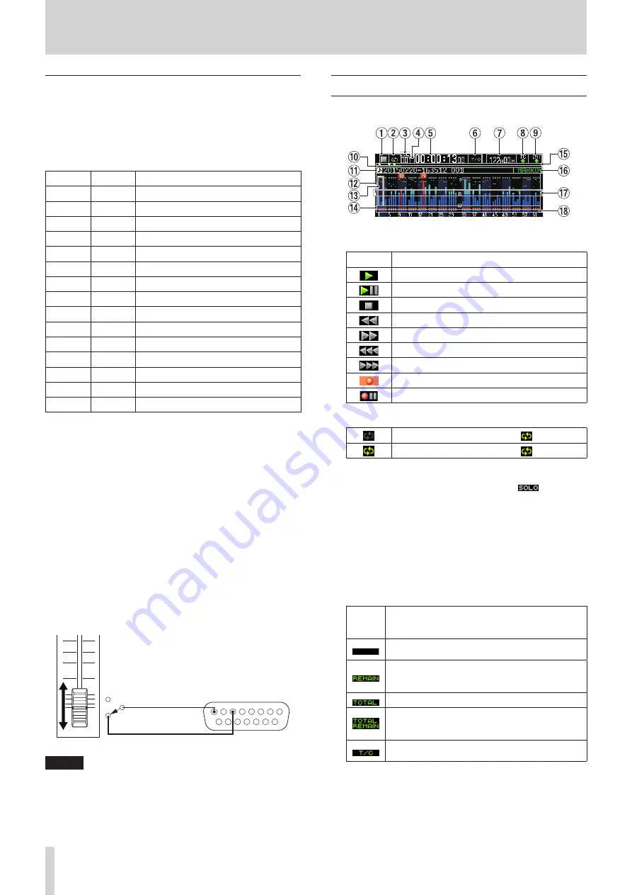
Note about the PARALLEL connector
The
PARALLEL
connector on the back of the unit allows
external control of it.
You can set the functions of the
PARALLEL
connector on the
PARALLEL INPUT
and
PARALLEL OUTPUT
pages. (See
“PARALLEL connector settings” on page 38.)
The factory default pin assignments are as follows.
Pin No.
I/O
Function (default value)
1
O
OUTPUT AUX1 (STOP TALLY)
2
O
OUTPUT AUX2 (REC TALLY)
3
I
INPUT AUX1 (TAKE SKIP +)
4
I
INPUT AUX2 (TAKE SKIP −)
5
O
OUTPUT AUX3 (ERROR TALLY)
6
I
INPUT AUX3 (FADER REC)
7
I
INPUT AUX4 (REW)
8
GND
9
O
OUTPUT AUX4 (PLAY TALLY)
10
O
OUTPUT AUX5 (PAUSE TALLY)
11
I
INPUT AUX5 (F.FWD)
12
I
STOP
13
I
PLAY
14
I
INPUT AUX6 (PAUSE)
15
+5V
I: For command input and transport control
Internal circuit with +5V pull-up
Operates with low signal input of 50 msec or longer
When INPUT AUX is set to FADER REC, low signal input
starts recording and high signal input stops recording.
When INPUT AUX is set to FADER START, low signal input
starts playback and high signal input pauses playback.
O: For command and tally output
Internal circuit is open collector (10Ω output impedance)
Outputs low command during operation
20V dielectric strength, 35mA maximum current
+5V: 50mA maximum supplied current
The following example is of a connection that controls recording
and playback of this unit by level, using fader starts and stops
and FADER REC commands.
START
STOP
PARALLEL
STOP
Pin 8 : GND
Pin 6 : REC
NOTE
Setting multiple FADER REC and FADER START settings to
INPUT AUX is not possible.
Home Screen
The following information is shown on the unit's display.
1
Transport status
This icon shows the current transport status.
Icon
Meaning
Playing back
In playback standby
Stopped
Searching backward
Searching forward
Searching backward (high speed)
Searching forward (high speed)
Recording
In record standby
2
Repeat status
When repeat playback is off, the icon is unlit.
When repeat playback is on, the icon is lit.
3
Solo status
When the solo selection frame is white, the
icon blinks.
4
Take number
This shows the number of the take playing or being
recorded.
5
Time counter
This shows the elapsed recording/playback time of the take
or the timecode time.
6
Time display mode
This icon shows the current time display mode.
Time
display
mode
Meaning
This shows the elapsed time from the beginning
of the take.
This shows the remaining time until the end of
take. When recording, this shows the remaining
time until the maximum file size is reached.
This shows the total take elapsed time.
During playback, this shows the total take
remaining time. When recording, this shows the
remaining available recording time.
This shows the timecode time of the recording/
playback take.


