22
TASCAM US-20x20
6 – Using the Settings Panel
zation becomes impossible, “Unlock” will appear for the
Digital Input Status item and the unit's MODE indicator will
blink.
•
When connecting multiple digital devices to the US-20x20,
synchronize them to a system word clock and input word
clock supplied by the master clock device to the US-20x20.
2
Internal Sample Rate
Set the sampling frequency of the unit's internal clock.
Options: 44.1kHz, 48kHz, 88.2kHz, 96kHz, 176.4kHz,
192kHz
NOTE
When the unit is in AUDIO I/F mode, you cannot set the
Internal Sample Rate.
3
Coaxial Digital Output Format
Use this to set the digital output format.
Options: S/PDIF, AES/EBU
4
Digital Input (176.k/192k Hz)
Use this to set the digital input destination. (Only when
176.4/192 kHz)
Options: COAXIAL, OPTICAL 1/2
5
Buffer Size (Windows only)
The Windows driver for the unit stores the audio signals
transferred to and from the computer temporarily in a
buffer. This buffer size can be adjusted.
Smaller buffer sizes result in less audio signal delay (latency),
but require high-speed processing by the computer.
If the processing cannot keep up, for example, due to other
system operations, clicking and popping noises might occur
and the audio signal might even drop out.
Increasing the buffer size will stabilize operation and
suppress negative effects on audio signals, but the delay in
audio signals sent to the computer will increase.
You can use the slider on the panel to adjust the buffer size,
according to the use conditions.
Use the slider to select fixed values that increase from left to
right.
Options: 64 Samples, 128 Samples, 256 Samples, 512
Samples, 1024 Samples, 2048 Samples
NOTE
When the unit is in MIC PRE or MIXER mode, you cannot set
the Buffer Size.
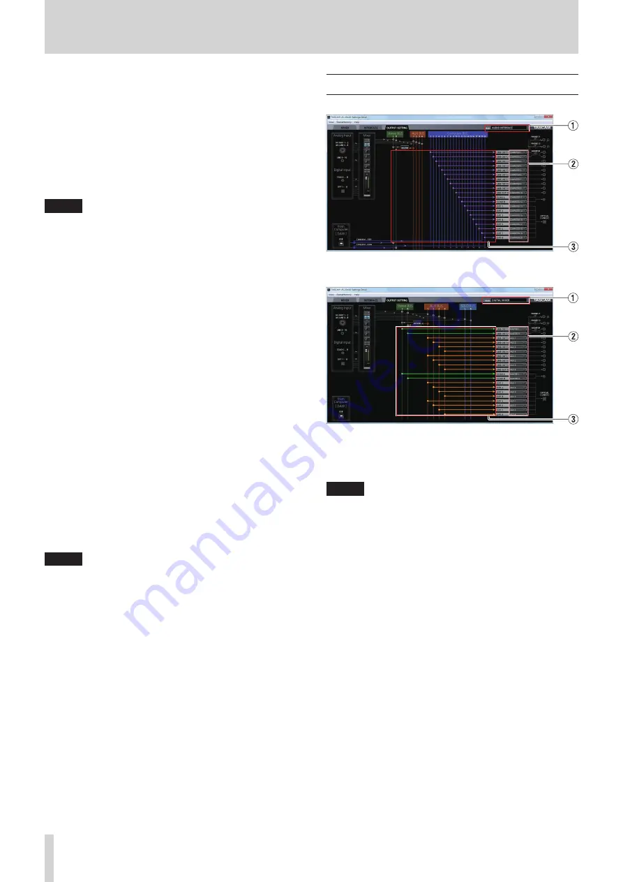
OUTPUT SETTING page
Windows Settings Panel page in AUDIO I/F mode
Windows Settings Panel page in MIXER mode
On the “OUTPUT SETTING” page, set the signal lines output from
the unit's output jacks.
NOTE
When the unit is in MIC PRE mode, you cannot change
settings in the output signal selection area of the “OUTPUT
SETTING” page. (See “Using the unit as a microphone
1
Mode
This shows the operation mode of the unit set using the
MODE button on its front panel.
2
Output signal selection area
Click the output signal selection area to open a pull-down
menu from which you can select the signal you want to
output from the options. The options shown depend on the
operation mode.
Options:
MASTER L/MASTER R
Output the L/R signals from the Stereo BUS
AUX 1–AUX 4
Output the signals from an AUX BUS (1–4)
COMPUTER 1–COMPUTER 20
When the operation mode is AUDIO I/F, signals are
output from Computer BUS (1–20)
SOLO L/SOLO R:
When the operation mode is MIXER, signals are output
from SOLO BUS (L/R).
Содержание Celesonic us-20x20
Страница 40: ...40 TASCAM US 20x20 11 Specifications Block diagrams Mic preamp mode...
Страница 41: ...TASCAM US 20x20 41 11 Specifications Audio interface mode...
Страница 42: ...42 TASCAM US 20x20 11 Specifications Digital mixer mode...
Страница 43: ...TASCAM US 20x20 43 11 Specifications Level diagrams...


