background image

6. Installation 

 CMS 3.0 Series Operation Manual  rev 3.0.0

9


6.2. Installation Guide for Sheetrock Ceilings 

1.  Position the cutout template (self adhesive backed) on the 
ceiling. (Fig.1)

 
2. Cut out the hole in the ceiling using a pad saw following the 
broken line indicated on the template then slide the C-Ring into 
the ceiling, aligning it over the cut-out hole. (Fig.2) 

 
3. Go to section 7 for wiring and set-up instructions then return 
to point 4 below. 

 
4. Slide the speaker assembly through the hole. Turn the screws 
(denoted “Screw Fix”) clockwise on the front of the speaker 
to extend the mounting wings. Tighten the screws until a firm 
grip is achieved. (NOTE: Screws have a PoziDriv head; use of a 
PoziDriv driver is recommended). If using a power driver, Tannoy 
recommends a torque setting of 1.5 Nm. (Fig.3)

DO NOT OVERTIGHTEN!

 
5. Attach the nylon safety to the hooks on the front baffle  
before attaching the grille by presenting it to the speakers and 
allowing the magnets to pull it into position (Fig.4). (With the  
CMS 403DCe/ICTe, the grille is already fitted to the product.)

NOTE ON INSTALLATION OF CMS 403DCe/ICTe:

Before tightening the screws in step 4, swivel the speaker in the 
desired direction. When the screws are tightened, the speaker will
lock into position. Replace the front trim to conceal the mounting
screws.

Fig.1

Fig.2

Fig.3

Fig.4

Содержание CMS 3.0 series

Страница 1: ...Operation Manual CMS3 0Series In CeilingLoudspeakers...

Страница 2: ...2 CMS3 0SeriesOperationManual rev3 0 0...

Страница 3: ...6 5 Accessories 7 6 Installation 8 6 1 Installation Guide for Suspended Ceilings 8 6 2 Installation Guide for Sheetrock Ceilings 9 6 3 Installation Guide for Optional Plaster Ring 10 6 4 Installation...

Страница 4: ...dary support line should be attached from the back of the driver chassis to a source point on the ceiling Please consult the relevant construction codes in your region When using a power driver to ins...

Страница 5: ...pes specified Some variations will be apparent in some models but differences are not critical for installation purposes except as noted 4 1 BlindMount The blind mount models are supplied with a pre f...

Страница 6: ...ev3 0 0 4 3 Pre installbackcan Optional pre install PI backcan for PI models NOTE The CMS 603DC ICT and CMS 803DC models have the transformer pre attached to the inside of the backcan The CMS 503DC IC...

Страница 7: ...cessories OptionalAccessories C Ring Grille Paint Mask Cut out template 60 W Transformer Note For use with CMS 803 PI in distributed lines without backcans Tile bridge kit Note A tile bridge kit must...

Страница 8: ...e hole Turn the screws denoted Screw Fix clockwise on the front of the speaker to extend the mounting wings Tighten the screws until a firm grip is achieved NOTE Screws have a PoziDriv head use of a P...

Страница 9: ...extend the mounting wings Tighten the screws until a firm grip is achieved NOTE Screws have a PoziDriv head use of a PoziDriv driver is recommended If using a power driver Tannoy recommends a torque s...

Страница 10: ...a PoziDriv driver is recommended If using a power driver Tannoy recommends a torque setting of 1 5 Nm Fig 3 DO NOT OVERTIGHTEN 5 Attach the nylon safety to the hooks on the front baffle before attachi...

Страница 11: ...hed to the PI backcan Fig 2 METHOD 3 a Attach the PI backcan to the optional pre mount ring plaster ring using the fixings provided with the pre mount ring Fig 3 b Next secure the wings of the pre mou...

Страница 12: ...g cover which holds the cable clamp in place and replace it with a conduit squeeze connector Fig 5 METHOD 2 You can use any of the three knock out points at the sides of the PI backcan 19 mm 22 mm or...

Страница 13: ...Screw Fix clockwise on the front of the speaker to extend the mounting wings Tighten the screws until a firm grip is achieved NOTE Screws have a PoziDriv head use of a PoziDriv driver is recommended...

Страница 14: ...tary switch on the front of the unit to select low impedance LoZ mode or high impedance 70 V or 100 V for distributed applications THE SPEAKER IS SUPPLIED IN LOW IMPEDANCE MODE NEVER CONNECT THE SPEAK...

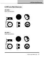
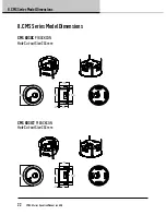
Страница 15: ...nsions CMS3 0SeriesOperationManual rev3 0 0 15 8 CMSSeriesModelDimensions CMS403DCe HoleCut outSize 187mm 205 0 8 07 34 2 1 35 147 6 5 81 181 1 7 13 CMS403ICTe HoleCut outSize 187mm 205 0 34 2 1 35 14...

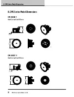
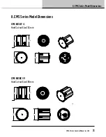
Страница 16: ...3 0SeriesOperationManual rev3 0 0 8 CMSSeriesModelDimensions CMS503DCBM HoleCut outSize 190mm 205 9 8 11 181 3 7 14 205 3 8 08 188 0 7 40 4 5 0 18 CMS503ICTBM HoleCut outSize 190mm 205 9 8 11 181 3 7...

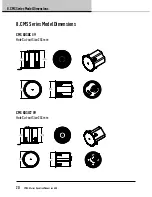
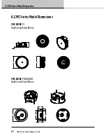
Страница 17: ...ions CMS3 0SeriesOperationManual rev3 0 0 17 8 CMSSeriesModelDimensions CMS503DCLP HoleCut outSize 253mm 274 0 10 79 98 6 3 88 4 2 0 17 244 3 9 62 CMS503ICTLP HoleCut outSize 253mm 274 0 10 79 98 6 3...

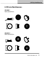
Страница 18: ...imensions 18 CMS3 0SeriesOperationManual rev3 0 0 8 CMSSeriesModelDimensions CMS503DCPI HoleCut outSize 190mm 205 9 8 11 133 3 5 25 4 2 0 17 CMS503ICTPI HoleCut outSize 190mm 205 9 8 11 131 7 5 19 4 2...

Страница 19: ...l rev3 0 0 19 8 CMSSeriesModelDimensions CMS503DCPIBACKCAN HoleCut outSize 190mm 288 0 11 34 256 0 10 08 8 8 0 35 136 2 5 36 153 5 6 04 186 4 7 34 CMS503ICTPIBACKCAN HoleCut outSize 190mm 288 0 11 34...

Страница 20: ...SeriesOperationManual rev3 0 0 8 CMSSeriesModelDimensions CMS603DCBM HoleCut outSize 253mm 273 3 10 76 4 2 0 17 255 8 10 07 244 3 9 62 274 0 10 79 CMS603ICTBM HoleCut outSize 253mm 273 8 10 78 4 1 0 1...

Страница 21: ...ons CMS3 0SeriesOperationManual rev3 0 0 21 8 CMSSeriesModelDimensions CMS603DCPI HoleCut outSize 253mm 274 0 10 79 4 1 0 16 244 3 9 62 100 0 3 94 CMS603ICTPI HoleCut outSize 253mm 100 0 3 94 4 1 0 16...

Страница 22: ...nual rev3 0 0 8 CMSSeriesModelDimensions CMS603DCPIBACKCAN HoleCut outSize 253mm 351 0 13 82 249 4 9 82 168 5 6 63 8 8 0 35 151 2 5 95 319 0 12 56 CMS603ICTPIBACKCAN HoleCut outSize 253mm 351 0 13 82...

Страница 23: ...esOperationManual rev3 0 0 23 8 CMSSeriesModelDimensions CMS603ICTLS HoleCut outSize 253mm 273 8 10 78 4 1 0 16 256 5 10 10 244 3 9 62 274 0 10 79 CMS803DCBM HoleCut outSize 295mm 319 0 12 56 327 7 12...

Страница 24: ...iesOperationManual rev3 0 0 8 CMSSeriesModelDimensions CMS803DCPI HoleCut outSize 295mm 319 0 12 56 286 4 11 27 125 6 4 94 5 2 0 20 CMS803DCPIBACKCAN HoleCut outSize 295mm 397 0 15 63 291 4 11 47 365...

Страница 25: ...8 CMSSeriesModelDimensions CMS3 0SeriesOperationManual rev3 0 0 25 8 CMSSeriesModelDimensions CMS803DCQ HoleCut outSize 295mm 319 0 12 56 327 7 12 90 5 2 0 20 310 5 12 22 286 4 11 27...

Страница 26: ...ended clamp torque 1 5 Nm Backcan Blind Mount BM Complete with fixed backcan Connectors Removable locking connector with screw terminals with loop through facility Compliance UL 1480 UL 2043 CE Dimens...

Страница 27: ...Max clamping range 0 0 mm 0 0 20 0 mm 0 79 Recommended clamp torque 1 5 Nm Connectors Removable locking connector with screw terminals with loop through facility Compliance UL 1480 UL 2043 CE Dimensio...

Страница 28: ...able locking connector with screw terminals with loop through facility Compliance UL 1480 UL 2043 CE Dimensions Bezel diameter 205 9 mm 8 11 BM Model Front of ceiling to rear of backcan 188 0 mm 7 40...

Страница 29: ...try Options Cable clamp squeeze connector for conduit up to 22 mm Connectors Removable locking connector with screw terminals with loop through facility Compliance UL 1480 UL 2043 CE Dimensions Bezel...

Страница 30: ...87 1 10 Connectors Removable locking connector with screw terminals with loop through facility Compliance UL 1480 UL 2043 CE Dimensions Bezel diameter 205 9 mm 8 11 BM Model Front of ceiling to rear...

Страница 31: ...Connectors Removable locking connector with screw terminals with loop through facility Compliance UL 1480 UL 2043 CE Dimensions Bezel diameter 274 0 mm 10 79 Front of ceiling to rear of backcan 98 6 m...

Страница 32: ...ocking connector with screw terminals with loop through facility Compliance UL 1480 UL 2043 CE Dimensions Bezel diameter 274 0 mm 10 79 BM Model Front of ceiling to rear of backcan 255 8 mm 10 07 BM M...

Страница 33: ...m 0 75 0 87 1 10 Connectors Removable locking connector with screw terminals with loop through facility Compliance UL 1480 UL 2043 CE Dimensions Bezel diameter 274 0 mm 10 79 BM Model Front of ceiling...

Страница 34: ...s Removable locking connector with screw terminals with loop through facility Compliance UL 1480 UL 2043 CE Dimensions Bezel diameter 319 0 mm 12 56 BM Model Front of ceiling to rear of backcan 310 5...

Страница 35: ...lamp squeeze connector for conduit up to 22 mm Connectors Removable locking connector with screw terminals with loop through facility Compliance UL 1480 UL 2043 CE Dimensions Bezel diameter 319 0 mm 1...

Страница 36: ...th the cone and roll surround Apply several thin coats of paint this will provide a better finish than one overly thick coat Painting the grille Carefully remove the acoustically transparent grille cl...

Страница 37: ...tomers One element of this commitment is our after sales support which now incorporates our extended Limited Warranty In the event of any concern that is not addressed by this extended Limited Warrant...

Страница 38: ...MS 503ICT PI BACKCAN CMS 603DC BM CMS 603ICT BM CMS 603DC PI CMS 603ICT PI CMS 603DC PI BACKCAN CMS 603ICT PI BACKCAN CMS 603ICT LS CMS 803DC BM CMS 803DC PI CMS 803DC PI BACKCAN CMS 803DCQ Is are in...

Страница 39: ...CMS3 0SeriesOperationManual rev3 0 0 39 Notes Notes...

Страница 40: ...us research and development The introduction of new materials or manufacturing methods will always equal or exceed the published specifications All specifications are subject to change without notice...

Отзывы: