


51
INSTALLATION INSTRUCTIONS
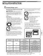
Gas Supply (cont.)
Gas Supply
Gas Piping
Pipe-Sizing Procedure – Example
The gas supply system must be properly sized to ensure
the proper operation of this tankless water heater as
well as all the gas appliances on the system. Failure to
ensure the gas system, (meter, regulators, and piping) are
properly sized could result in improper operation of this
or other gas appliances. Insufficient gas pressure/supply
can cause pilot outages, lockouts, or operating conditions
that could lead to an appliance failure, improper combus-
tion, carbon monoxide, sooting, or fire. Gas line sizing is
based on gas type, the pressure drop in the system, the
gas pressure supplied, and the gas line type. For gas pipe
sizing in the United States, refer to the National Fuel Gas
Code, (NFPA 54, ANSI Z223.1). For Canadian gas pipe siz-
ing, refer to the Natural Gas and Propane Installation Code
CAN/CSA B149.1.
These simplified instructions only address low pressure
gas systems using Schedule 40 Metallic Pipe (Black
Iron). For hybrid gas systems, high pressure main lines
with regulators at the appliances, gas systems piped with
corrugated stainless steel tubing (CSST), or Propane gas
systems.
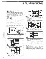
Determining the required regulator and
gas meter size.
Find the BTU capacity of each appliance on the system.
This information is located on a rating label attached to
the appliance. Total the BTU of all the appliances together
and divide that by the heating value of the fuel (for natural
gas the average is 1,024 or 2,546 for propane). This will
give you the total cubic feet per hour of gas required for
the system.
At your gas meter/regulator there will be a rating plate
that gives the cubic feet per hour capacity of that equip-
ment. If the total gas required for the system is greater
than the rating of the meter/regulator then the local gas
company will need to be contacted in order to upgrade the
meter/regulator for the system.
Gas Input of
Cubic Feet Water Heater (BTU/HR)
Per Hour (CFH) = Heating Value of Gas (BTU/FT
3
)
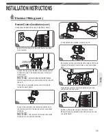
Determining the required pipe size.
The gas system is designed to operate at a certain maxi-
mum pressure drop. A pressure drop greater than what
is permissible can cause operational issues with the gas
appliances. The National Fuel Gas Code (NFPA 54, ANSI
Z223.1 2012) allows for three pressure drop levels, a 0.3
inch W.C., (see table 2); a 0.5 inch W.C., (see table 3) and
a 3.0 inch W.C., (see table 4) pressure drop for natural
gas. Only a 0.5 inch W.C. pressure drop is allowable with
Propane (see table 5). For Canadian installations the
maximum allowable pressure drop is 0.5 inch W.C., (see
table 3).
Measure the inlet gas pressure to the system using a ma-
nometer. For Natural Gas, if the inlet pressure is less than
8.0 inches W.C. then use Table 2 or 3 for your gas pipe
sizing. Table 4 can only be used if the inlet gas pressure
is 8.0 inches W.C. or greater. Table 4 cannot be used for
Canadian installations.
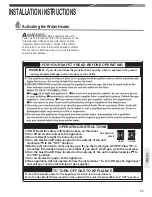
The gas piping system consists of a main trunk line that
runs from the meter/regulator and branch lines that run
from the trunk line to the individual appliances. A branch
may carry gas for more than one appliance.
The trunk line must be sized to carry the entire load of all
the gas appliances on the system. As with determining
the meter/regulator size, total the BTU of all the appli-
ances together and divide that by the heating value of
the fuel (for natural gas the average is 1,024 or 2,546 for
propane). This will give you the total cubic feet per hour
of gas required for the trunk line. Measure the total length
of the line Refer to Table(s) 2, 3, or 4 and find the number
closest to but higher than the total cubic feet per hour
requirement calculation. This will tell you the minimum
size that the trunk line must be.
Each branch line must be sized to carry the load of the
appliance(s) attached to it. If more than one appliance is
on a branch total the BTU and as with the trunk line divide
that by the heating value of the fuel. Refer to Table(s) 2,
3, or 4 and find the number closest to but higher than the
total cubic feet per hour requirement calculation for the
branch and appliance(s). This will tell you the minimum
size for that branch line and appliance.


