17
2.3
Switches Definitions
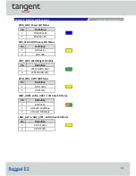
AT_ATX1: AT / ATX Power Mode Switch
CLR_CMOS1: Clear BIOS Switch
2.4
Connectors Definitions
PWR_SW1: Power Button
RESET1 : Reset Button
USB3_1: USB3.0 Connector, Type A
USB3_2: USB3.0 Connector, Type A
Chapter 2: Switches and Connecto
Rugged E3 l User’s Manual
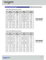
Pin
Definition
Pin
Definition
1
+5V
6
U
2
USB2_D6-
7
GND
3
8
USB3_TX6-
4
GND
9
U
5
USB3_RX6-
Pin
Definition
1
RESET
2
GND
Switch
Definition
Off
Normal Status (Default)
ON
Clear BIOS
Switch
Definition
1-2 (Left)
AT Power Mode
2-3 (Right)
ATX Power Mode
(
Default
)
Pin
Definition
Pin
Definition
1
NC
4
GND
2
Power Button
5
NC
3
NC
6
GND
Pin
Definition
Pin
Definition
1
+5V
6
U
2
USB2_D5-
7
GND
3
8
USB3_TX5-
4
GND
9
U
5
USB3_RX5-
Содержание Rugged E3
Страница 1: ......
Страница 7: ...Product Introductions...
Страница 12: ...12 1 4 Mechanical Dimensions 1 4 1 Rugged E3 Unit mm Chapter 1 Product Introductions Rugged E3 l User s Manual...
Страница 13: ...13 Switches and Connectors...
Страница 14: ...14 2 1 Switch and Connector Locations 2 1 1 Top View Chapter 2 Switches and Connecto Rugged E3 l User s Manual...
Страница 15: ...15 2 1 2 Bottom View Chapter 2 Switches and Connecto Rugged E3 l User s Manual...
Страница 33: ...BIOS Setup 33...
Страница 53: ...53 Copyright 2016 Tangent Inc All Rights Reserved www tangent com...


