background image

6

23

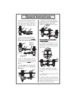
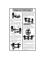
Valve Assembly:

17. Replace no.

21 

and no.

22

 on both 

sides of no.

16

 and tighten bonnets 

suf

fi

 ciently by hand to position 

valves.

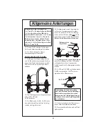
21. Tighten 

packing nut

 down 

against 

locknut

 using two wrenches. 

Hold 

locknut

 while rotating 

packing 

nut.

18. Remove 

packing nut/locknut as-

sembly

 from both no.

21

 and no.

22

.

19. Slip no.

23 

over each no.

21

,

22

Make sure 

washer

 is in place.

24, 27, 28

Note: It may become necessary 
to tighten bonnets and packing 
nuts to stop leakage from outlet 
or around spindle assembly

23

packing nut

locknut

bonnet

packing

22. Attach no.

24

 to no.

21

,

22

 and 

screw in no.

28

. Place no.

27

 in the 

appropriate no.

24

.

23. Wrench tighten all parts if neces-
sary.
24. Turn on water supply and check 
for leaks.

Note: When tightening no.

17

 and 

no.

18

, make sure that both no.

16

’s 

are located at the same height 
above sink level. Tighten no.

17

 and 

no.

18 

before tightening no.

19 

and 

no.

20

. Verify dimension from deck 

to top of no.

16

. Adjust no.

17

 and 

no.

20

 if required.

15. Tighten second (bottom) no.

11


against no.

9

 with a wrench.

16. Tighten no.

13

 on both no.

16

’s 

with a wrench.

20. 

Packing nut

 and 

locknut

 should 

be loosely assembled before replac-
ing into no.

21

,

22

. Hand-tighten 

locknuts

 only against no.

23

Do not 

use a wrench.

sink

21/22

16

General Instructions

Содержание B-0850 Series

Страница 1: ...ser are the responsibility of the purchaser Repair and or replacement shall be made within a reasonable time after receipt by T S of the returned product This warranty does not cover Items which have received secondary finishing or have been altered or modified after purchase or for defects caused by physical abuse to or misuse of the product or shipment of the products Anyexpresswarrantynotprovid...

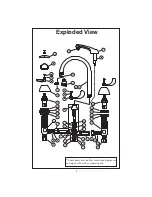
Страница 2: ...ems are listed for instructional purposes and may not be sold as separate parts 2 21 11 6 20 10 13 15 13 14 7 35 16 8 1 2 19 18 37 17 38 12 23 15 34 31 36 32 33 30 29 14 13 19 27 20 28 18 24 17 9 5 6 3 16 13 7 4 22 26 25 39 ...

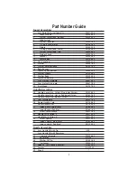
Страница 3: ...78 40 22 Asm Eterna LH Spindle 006477 40 23 Escutcheon 001257 45 Handle Assemblies 24 Handle Lever Zinc Cold w Blue Index Screw 001636 45 Handle Lever Zinc Hot w Red Index Screw 001637 45 Handle Lever Zinc Blank w Screw 001638 45 25 Four Arm Handle 002521 45 26 Dome Handle Cold 001784 40 Dome Handle Hot 001783 40 27 Index Button Blue Cold 001660 45 Index Button Red Hot 001661 45 28 Screw Lever Han...

Страница 4: ... 10 and first no 11 as shown 12 10 11 hand tighten 9 6 4 Screw second no 11 about half way up shank and slide no 9 and no 6 greased up onto bottom of no 12 shank greased 21 22 20 19 18 17 15 14 13 16 1 Installation Nozzle Note Nozzle should be installed first 1 Apply Teflon tape or pipe joint compound to threaded end of no 32 33 2 Tighten no 32 33 firmly by hand into no 12 2 5cm Ø 3 5cm Ø 3 5cm Ø ...

Страница 5: ...r lavatory and fit no 4 onto no 12 Make sure greased no 6 is in place 9 Loosely tighten no 17 and no 18 against bottom of sink Do this for both sides 16 12 18 17 4 6 16 6 8 4 6 3 2 5 12 12 Tighten no 10 and top no 11 on underside of lavatory sink with a wrench 13 Tighten no 2 on bottom of no 12 with a wrench 14 Tighten no 17 and no 18 on both no 16 s underneath lavatory sink also tighten no 19 and...

Страница 6: ...net packing 22 Attach no 24 to no 21 22 and screw in no 28 Place no 27 in the appropriate no 24 23 Wrench tighten all parts if neces sary 24 Turn on water supply and check for leaks Note When tightening no 17 and no 18 make sure that both no 16 s are located at the same height above sink level Tighten no 17 and no 18 before tightening no 19 and no 20 Verify dimension from deck to top of no 16 Adju...

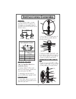
Страница 7: ...4 Atornille la segunda parte No 11 cerca de el medio en el asta y deslice las partes No 9 y No 6 engrasadas hacia arriba por el fondo de el asta de la parte No 12 Instalación Boquilla Nota Las boquillas deben de ser instaladas primero 1 Aplique cinta de Teflon o com puesto de coyuntura al extremo con rosca de la parte No 32 33 2 Firmemente apriete a mano la parte No 32 33 entre la parte No 12 2 5c...

Страница 8: ...rtes No 17 y No 18 contra el fondo de lavatorio Haga esto para ambos lados 12 Por debajo del lavatorio Con una llave aprete la parte No 10 y una de las partes No 11 la de arriba contra la parte poste rior de el lavatorio 13 Con una llave aprete la parte No 2 contra el fondo de la parte No 12 14 Con una llave aprete las partes No 17 y No 18 en ambas partes No 16 por debajo de el lavatorio tambien a...

Страница 9: ... la apropiada parte No 24 23 Si es necesario aprete todas la partes con llave 24 Abra la fuente de agua e inspeccione por filtracciones Nota Cuando este apretando las partes No 17 y No 18 asegurese que ambas partes No 16 esten localizadas a la misma altura a nivel sobre el lavatorio Aprete las partes las partes No 17 y No 18 antes de apretar las partes No 19 y No 20 Verifique la dimensión desde la...

Страница 10: ... Nº 12 L Installation De L Ajutage Noter Les ajutages devoir être installer au début 1 Appliquer le ruban en Téflon ou le composé pour les tuyaux à l extrémité de Nº 32 33 avec les filets 2 Resserrer Nº 32 33 fermement par le main dans Nº 12 2 5cm Ø 3 5cm Ø 3 5cm Ø 20 to 30cm 10 to 15cm 1 Ø 1 3 8 Ø 1 3 8 Ø 4 to 6 8 to 12 2 12 1 resserrer par le main avec de la graisse 12 10 11 9 6 3 Installer Nº 1...

Страница 11: ...ns bien serrer Nº 17 et Nº 18 contre le fond de l évier Faire la même chose pour chaque côté 12 Resserrer Nº 10 et Nº 11 le haut sur le fond de l évier avec une clef anglaise 13 Resserrer Nº 2 sur le fond de Nº 12 avec une clef anglaise 14 Resserrer Nº 17 et Nº 18 sure les deux Nº 16 au fond de l évier aussi resser rer Nº 19 et Nº 20 sur le côté en haut de l évier avec une clef anglaise L Assembla...

Страница 12: ... le Nº 24 approprié 23 Resserrer tous les parties avec une clef anglaise si nécessaire 24 Recommencer l eau et vérifier s il y a des fuites l écrou d emballage le contre écrou le capot d emballage Noter En resserrant Nº 17 et Nº 18 soyez certain que les Nº 16 s tous les deux se situer au même niveau au dessus de l évier Resserrer Nº 17 et Nº 18 avant vous resserrer Nº 19 et Nº 20 Vérifier la dimen...

Страница 13: ...igt installieren mit der Hand fest drehen 4 Zweite Nr 11 ungefähr auf die Hälfte des Schafts einschrauben und Nr 9 und Nr 6 gefettet über den unteren Teil des Schafts Nr 12 schieben fetten Installation der Strahldüse Hinweis Die Strahldüse sollte als erstes installiert werden 1 Tragen Sie Teflonband oder Rohrkitt zum Gewindeende der Nr 32 33 auf 2 Drehen Sie Nr 32 33 mit der Hand fest in Nr 12 2 5...

Страница 14: ...tziehen und oberen Teil von Nr 11 auf der Unterseite des Wasch beckens mit einem Schraubenschlüssel festziehen 13 Nr 2 am unteren Ende von Nr 12 mit einem Schraubenschlüssel festziehen 14 Nr 17 und Nr 18 auf beiden Nr 16 unter dem Waschbecken festziehen Eben falls Nr 19 und Nr 20 auf der Oberseite des Waschbeckens mit einem Schrauben schlüssel festziehen Abschließende Zusammensetzung des Mitteltei...

Страница 15: ... einschrauben Nr 27 in die en tsprechende Nr 24 einsetzen 23 Falls erforderlich alle Teile fest mit dem Schraubenschlüsssel zudrehen 24 Wasserzufuhr andrehen und auf Dich tigkeit prüfen 20 Dichtungsmutter und Gegenmutter sollten lose zusammengesetzt werden bevor sie wieder in Nr 21 Nr 22 eing esetzt werden Mit der Hand nur die Ge genmuttern gegen Nr 23 festschrauben Keinen Schraubenschlüssel benut...

Страница 16: ... Box 1088 T S Brass Europe Travelers Rest SC 29690 De Veenhoeve Phone 864 834 4102 Oude Nieuwveenseweg 84 Fax 864 834 3518 2441 CW Nieuwveen E mail tsbrass tsbrass com The Netherlands RELATED T S BRASS PRODUCT LINE B 0868 04 Medical Lavatory Faucet with Pop Up Waster B 0865 04 Medical Lavatory Faucet Concealed Body ...

Отзывы: