

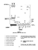


Head amplitude can be verified by establishing
a nominal value of amplitude for the diskette on
a known working drive. In all cases, amplitudes
greater than 200 millivolts peak-to-peak are ac
ceptable. If head amplitude is suspected as being
faulty, refer to the troubleshooting guide.
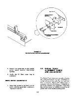
1. Remove the alignment diskette, and
insert a nonwrite protected diskette into
the drive.
2. Set up the oscilloscope:
Channel A: Test Point 1
Channel B: Test Point 2
Vertical Amplitude: 50 millivolts per
division
Ground: Test Point 10
Read Differentially: A plus B, B inverted
Time Base: 20 milliseconds per division
External Trigger: Test Point 7
3. Seek to Track 39.
4. Write a 2F, all ones, pattern on Head 0.
5. Verify the amplitude is 200 millivolts or
greater, peak-to-peak.
6. Write a 2F, all ones, pattern on Head 1.
7. Verify the amplitude is 200 millivolts or
greater, peak-to-peak.
5.12 CONE CENTERING CHECK
Cone centering is the ability of the cone clamp
ing mechanism to center the diskette on the
hub, causing it to rotate concentrically. This
check and adjustment should be made whenever
the cone lever assembly has been removed or re
placed. If the cone centering cannot be adjusted,
verify the measurement with a second diskette,
otherwise refer to the troubleshooting guide.
1. Set up the oscilloscope:
Channel A: Test Point 1
Channel B: Test Point 2
Vertical Amplitude: 100 millivolts per
division
Ground: Test Point 10
Read Differentially: A plus B, B inverted
Time Base: 20 milliseconds per division
External Trigger: Test Point 7, positive
edge
2. Apply power to the drive.
3. Select the drive.
4. Seek to Track 0.
5. Write a 2F pattern on Head 0.
6. Measure the amplitude of the signal by
positioning the deepest dip in the signal
on the center vertical graticule.
7. Release the front latch, and remove the
diskette.
8. Reinsert the diskette, and close the front
latch.
9. Repeat Steps 7 and 8 until the deepest
dip in the waveform is produced.
10. Measure the amplitude of the deepest
dip.
11. Divide this measurement by the mea
surement in Step 6, and multiply it by
100. This result should be above 85
percent.
12. The signal amplitude should not decrease
below 85 percent of the average ampli
tude at any point on the track.
5-14
Содержание TM100-1
Страница 8: ......
Страница 11: ...FIGURE 1 1 DISK DRIVE ...
Страница 12: ......
Страница 18: ......
Страница 29: ...WRITE PROTECT TAB WRITE PROTECT TAB FIGURE 3 5 WRITE PROTECT TAB ...
Страница 34: ...FIGURE 4 4 INTERCONNECT BLOCK DIAGRAM 4 4 ...
Страница 58: ...CARRIAGE ASSEMBLY FIGURE 5 14 UPPER ARM AND SCREWS ...
Страница 66: ...FIGURE 6 2 LOGIC CIRCUIT BOARD MOUNTING 6 8 ...
Страница 72: ...E RIN G C O N E SH A FT FIGURE 6 7 CONE S COMPONENT PARTS 6 14 ...
Страница 76: ...FIGURE 6 13 INDEX EMITTER SENSOR S MOUNTING AND CABLE HARNESSING 6 18 ...
Страница 79: ...FIGURE 6 16 DRIVE MOTOR HARNESSING AND MOUNTING 6 21 ...
Страница 82: ...FIGURE 6 19 TRACK 0 ADJUSTMENT SCREW 6 24 ...
Страница 84: ...FIGURE 6 21 WRITE PROTECT MOUNTING ADJUSTMENT SCREWS FIGURE 6 22 WRITE PROTECT CABLE HARNESSING 6 26 ...
Страница 86: ...FIGURE 6 24 UPPER ARM SCREWS 6 28 ...
Страница 87: ...MOUNTING FIGURE 6 26 FELT PAD ON UPPER ARM 6 29 ...
Страница 90: ......
Страница 92: ...A 2 ...
Страница 93: ...A 3 ...
Страница 94: ......
Страница 99: ...l a n d e i n CORPORATION LOGIC CIRCUIT BOARD SCHEMATIC 180011 REV F SHEET 2 OF 3 B 5 ...
Страница 100: ... SV SHEET 3 OF 3 B 6 ...