background image

29

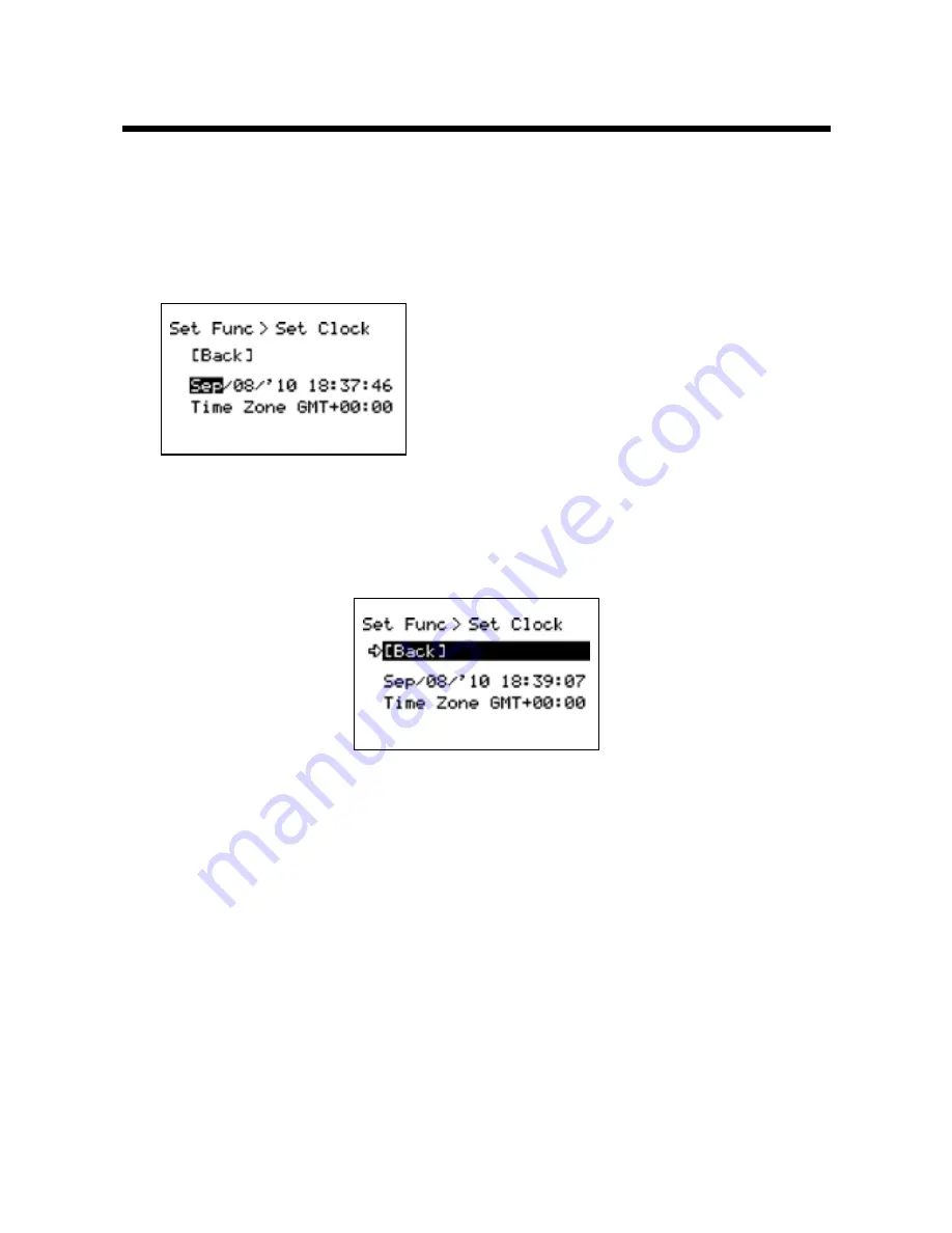
Setting the Date and Time

Follow the procedure below to make clock settings for the Unit. 

11 

In the Main Menu, go to [Set Functions] and select [Set Clock].

21 

Set the desired values.

(1) Moving the Operation Dial up and down 

will change the selection item of the 

display in the order of month, day, year, 

hour, and minute1 By pressing the dial, the 

value for that item will flash1

(2) Change the value by moving the dial up 

and down1 Press the dial again to set the 

selected value and move to the next 

settings item1

31 

After having completed the clock settings, move the arrow to [Back] and 
press the dial to return to the Menu Window.

[Time Zone]

By setting the region in which the Unit will be used the time difference will be 
automatically set. Daylight Savings Time settings must be set manually. 

-  Please make sure that the date and time settings in the Unit is correct, if it is  

not, the recording start time and recording time of downloaded data will be 
incorrect.

-  Clock settings for the Unit can also be made from your computer by using the 

software supplied with the Unit. For more details, see the [Help] Menu in the 
supplied software or the User’s Manual that accompanies it.

Содержание RTR-500DC

Страница 1: ...Manual Thank you for purchasing our product This manual explains in brief how to get an RTR 500DC unit ready for use and how to install the software Details about how to use the software RTR 500DC fo...

Страница 2: ...subject to change without notice On screen messages in this manual may vary slightly from the actual messages Please notify the shop where you purchased this product or T D Corporation of any mistake...

Страница 3: ...stand the contents Explanation of Symbols Explanation of Warning Symbols DANGER These entries are actions that absolutely under no circumstance should be taken The taking of such an action may cause s...

Страница 4: ...Store RTR 500DC main units batteries and communication cables out of the reach of children It is dangerous to touch or swallow batteries Connecting a communication cable that is connected to a PC or...

Страница 5: ...be used for period of time for safety reasons please remove the battery If left in the unit it may leak and lead to malfunctioning Condensation may occur if the unit is moved from one environment to a...

Страница 6: ...c fields It may cause damage In places exposed to water leakage It may cause damage or electrocution In areas exposed to static electricity It may cause damage In areas exposed to vibration It may cau...

Страница 7: ...ch can be determined by turning the equipment off and on the user is encouraged to try to correct the interference by one or more of the following measures Reorient or relocate the receiving antenna I...

Страница 8: ...t USB Device Driver 12 the RTR 574 Repeater USB Device Driver 14 Checking a USB Device Driver 16 Re installing the USB Device Driver 19 Explanation of the Button Functions 23 How to Use the Operation...

Страница 9: ...eadings 38 Monitor Mode Display 39 RU Settings Start Stop Recording Remote Unit 40 Record Settings 40 Visitor Entry Entry Release Visitor Remote Unit 41 Accept Visitor RU Remote Unit 41 Release One AL...

Страница 10: ...tion the USB driver may not properly install If you have connected the product to a PC without first installing the driver please make sure to press Cancel in the Installation Wizard window when it po...

Страница 11: ...nits via our exclusive short range wireless technology The RTR 500DC also allows you to wirelessly control recording settings and start recording as well as other functions of the Data Loggers Communi...

Страница 12: ...puter Besides controlling the collection of data the RTR 500DC can manage recording settings such as Programmed Recording Settings and Immediate Record This enables the user to easily control various...

Страница 13: ...mal conditions using a new batteries This is in no way or manner a guarantee of battery life Auto Power Off Function To save battery energy the RTR 500DC will automatically be turned off when not in u...

Страница 14: ...he package Data Collector RTR 500DC x 1 Antena x1 Software CD ROM x 1 RTR 500DC for Windows USB Communication Cable x 1 AAA Alkaline Batteries x 2 Introductry Manual and Warranty x 1 Connecting the An...

Страница 15: ...Unit mm Antenna Connector Antenna Operation Dial USB cable connection jack LCD Display RS 232C Communication cable connection jack List Button AC adaptor connection jack Collect Button Battery Compart...

Страница 16: ...may not operate properly Make sure to check that the OS you are running and RTR 500DC for Windows are compatible1 Microsoft Windows 7 32 64bit English Microsoft Windows Vista 32bit English Microsoft...

Страница 17: ...n Windows 2 Place the supplied software CD into the CD ROM drive The Install Program window will appear soon In Windows Vista or Windows 7 if the Auto Play window appears click on Run Start exe If the...

Страница 18: ...nse agreement if you accept the terms Click the Next button 6 The Choose Destination Location window will appear Click the Next button By clicking the Change Button it is possible to change the instal...

Страница 19: ...s XP Click the Continue Anyway Button For Windows Vista and Windows 7 Click the Install Button 8 After installation has been completed RTR 500DC for Windows will be registered in the Window s Start Me...

Страница 20: ...rocedure1 Upon connecting a Unit to your PC the New Hardware Detection Wizard will automatically open Please carry out the procedures on the following pages to install the USB Device Drivers for the B...

Страница 21: ...ould carry out the following procedure to install the USB Device Driver 1 By connecting a Base Unit to your computer the New Hardware Detection Wizard will automatically open The Wizard window will on...

Страница 22: ...ation process will begin If a warning message window appears click the Continue Anyway button and continue with the installation 3 Once the completion message appears installation has finished Click t...

Страница 23: ...g procedure to install the USB Device Driver 1 By connecting a Remote Unit RTR 574 or a Repeater to your computer the New Hardware Detection Wizard will automatically open The Wizard window will only...

Страница 24: ...inue Anyway button and continue with the installation 3 Once the completion message appears installation has finished Click the Finish Button See page from 16 of this Manual for about how to confirm t...

Страница 25: ...ne device at a time1 The checking procedure is the same for the Base Unit Remote Units and Repeaters Check using the following steps 1 Open the Device Manager window Procedure example In the Windows S...

Страница 26: ...b Click the Device Manager Button 2 Connect the target Unit to the computer with a USB cable and look at the icon displayed in the Device Manager window in order to check whether or not the USB Device...

Страница 27: ...th an or an the PC is not properly recognizing the Unit Windows XP Windows Vista Windows 7 3 If your PC does not properly recognize a Unit please re install the USB Device Driver by following the dire...

Страница 28: ...evice Driver 1 Right click on the icon 2 From the pop up menu click on Properties 3 When the following window appears click on the Reinstall Driver button to display the Wizard window General Tab Wind...

Страница 29: ...p 6 Check the Install from a list or specific location Advanced Click the Next Button Check the Include this location in the search Click the Browse Button 5 If you are using Windows Vista or Windows...

Страница 30: ...nstalled and specify Device Driver as the driver location Click the OK button to return to the Wizard window 7 In the Wizard window check to make sure that the Driver is specified correctly Then click...

Страница 31: ...river installation Please move on to the next step Warning Message For Windows XP Click the Continue Anyway Button Click the Install Button For Windows Vista and Windows 7 9 After installation has bee...

Страница 32: ...communication the Select Group display will appear Allows you to swift scroll across data when viewing a graph or an event list The downloaded data list will be displayed Allows you to swiftly make ch...

Страница 33: ...value will become larger and by moving the dial down the value will become smaller Pressing in on the dial Switching the Power On You cannot switch the power OFF with the operation dial Press in on t...

Страница 34: ...indicate menus for Wireless Communication Items marked with indicate menus for Optical Wired Communication A indicates that there are more menu items above or below the to view When battery life goes...

Страница 35: ...ous measurement Data that has been downloaded to an RTR 500DC unit can be displayed in Graph form Current Readings Monitoring The RTR 500DC can be set to patrol and monitor Remote Units groups and dis...

Страница 36: ...ll be displayed to inform you it is time to replace the battery If battery life goes even lower the Unit will automatically go into sleep mode in order to save data In sleep mode the Unit cannot be tu...

Страница 37: ...Dial Press the Operation Dial or ON OFF Button Auto Power Off Function If the main unit is not in use for 3 minutes the power will be automatically switched off in order to save battery power If you w...

Страница 38: ...the next settings item1 333After having completed the clock settings move the arrow to Back and press the dial to return to the Menu Window Time Zone By setting the region in which the Unit will be u...

Страница 39: ...C for Windows or the Introductory manual that accompanies it Note Communication with a computer cannot be carried out while a wireles communication session is occuring For USB Communication between RT...

Страница 40: ...e cable connection is a D sub 9pin male Please connect to the place that has such a symbol Examples of Serial Port Symbols RS 232C Communication cable connection jack D Sub9 Pin male to PC Optional Se...

Страница 41: ...C 2 In order to carry out wireless communication register Groups and Remote Units Place the unit face down on the RTR 500DC Communication Cable to computer Note If light enters during communication an...

Страница 42: ...registered as Remote Units via the accompanying software RTR 500DC for Windows The following operations can be done using Wireless communication Download Recorded Data You can download data to the RTR...

Страница 43: ...on Cable for RTR 574 Connect using the optional communication cable TR 6C10 The following operations can be done using communication via cable or optical communication Download Recorded Data You can d...

Страница 44: ...o a number of RTR 500DC Units it is possible to check and control settings as well as download to any RTR 500DC Unit that carries that Remote Unit s registration information Note If you try to carry o...

Страница 45: ...om No Rpt No Repeter or Obey Reg Obey Register Before Period of Data You can set the period how many hours or days before now from which you wish to download data You can select from 1 to 47 hours in...

Страница 46: ...not enough memory remaining the message Memory Over will appear and downloading will stop Please save recorded data from the TR 57DCi to your PC and delete unnecessary data from the TR 57DCi to make s...

Страница 47: ...mote Units Therefore when making changes to the Set Number of Possible Registrations make sure to register no more than 120 Remote Units to the Group or use the Specify Group range as oulined below Sp...

Страница 48: ...r of the cordless handsets displaying a cross axle Recording Status Recordeing Mode Icon Recording Interval S Seconds M Minute Battery Status of Remote Unit Quantity of current record readings Value o...

Страница 49: ...Programmed Start Interval Recording Interval It is not possible to set it with the Unit The content set with the dedicated software is displayed Start Date and Time If you are making changes to a prog...

Страница 50: ...eted Vistor Entry Completed shows Serial No of Remote Unit and Unit Name on this Units has given automaticaly Duplication Vistor Entry Completed shows Serial No of Remote Unit and Unit Name on this Un...

Страница 51: ...art Interval Recording Interval Choose from 10 59 S seconds per second 1 60 M minutes per minute Start Date and Time If you are making changes to a programmed start make sure to set start time Recordi...

Страница 52: ...ation Dial you can scroll the cursor left and right to view the recording date and time and measurement for that point where the cursor is positioned 3 Recording Interval and Mode The Recording Interv...

Страница 53: ...PC When downloading recorded data from Remote Units for which Upper Lower Limits have been set the judgment result will be displayed automatically upon completion of the downloading and at the time of...

Страница 54: ...and press the Operation Dial Main Menu Select data 222Move the arrow to Select Delete and press the Operation Dial 333A confirmation screen will appear Select Execute to delete the selected data or B...

Страница 55: ...Set Functions and Set Temp Unit Current Setting Select 222Move the arrow to C or F and press the Operation Dial Default value F 333Move the arrow to and click on Back to return to the Main Menu Set B...

Страница 56: ...ion Dial up to make the display darker and down to make it lighter Default value 65 0 to 100 333Press the Operation Dial to return to the Main Menu Check Memory Checking Storage Capacity of the Unit 1...

Страница 57: ...ear Memory 222Press on the Execute Set Clock Making Clock Settings 111In the Main Menu open Set Functions and Set Clock 222Select the item you wish to change and press the Operation Dial 333Move the O...

Страница 58: ...e Operation Dial to confirm 333Move the arrow to Back and press the dial to return to the Main Menu Battery Voltage Checking Battery Voltage 111In the Main Menu open Set Functions and Battery Voltage...

Страница 59: ...ion of radio wave transmissions and when creating a new Group assign the units to an empty frequency channel The radio wave strength is displayed in a scale from 1 to 5 with the higher the number the...

Страница 60: ...wnloaded Start Downloading Data Canceled It is possible to cancel by pushing the operation dial while Downloading Monitor Mode Back Group List Back Group List Back All Groups Specify a Group Specify a...

Страница 61: ...tart Recording Stop Recording Back RU VRU List Back RU VRU List Back Time Execute Start Programmed immImmediate Interval 1 Recording Mode 1 YY MM DD XX XX XX 2 Back Execute Back Confirmatin Display 1...

Страница 62: ...ck Execute Back Execute Only the confirmation Gather Data Specify the period of data to be downloaded Upon completion of the download a graph will appear Recording Settings Back Execute Send Recording...

Страница 63: ...ct Delete Back Execute Set Functions Back Set Temp Unit Back C F Set Backlight Back OFF 1 to 100 Set Contrast Back 0 to 100 Check Memory Back Display Memory Usage Clear Memory Back Execute Set Clock B...

Страница 64: ...Contrast Adjustment Backlight Power 2 AAA Alkaline Batteries LR03 AAA Ni MH 1 2V batteries Optional AC adaptor AD 0638 USB Bus Power Battery Life 96 hrs under Continuous Operation Using 2 AAA Alkaline...

Страница 65: ...IC RSS 210 Frequency Range 902 to 928MHz Communication Range About 150m if direct and unobstructed Communication Time When downloading one Remote Unit at full storage capacity RTR 50x About 120 sec RT...

Страница 66: ...Type Specialized Connector D sub9pin 1500 TR 6C10 Cable Length 1 0m 40 in USB Communication Cable unit mm US 15C Cable Length about 1 5m 60in 1500 AC Adaptor AD 0638 Input AC100 240V Output DC6V 500m...

Страница 67: ...glish Website for your convenience Here you can find information about our company news products upcoming events software and Introductory manual downloads as well as other support Please stop by and...

Страница 68: ...4 Free repair is not available in the following cases even though it is within the warranty period 1 Trouble or damage was caused by careless operation natural disaster fire public pollution or use o...

Отзывы: