background image

TC36.NG03.C 010408-16

12

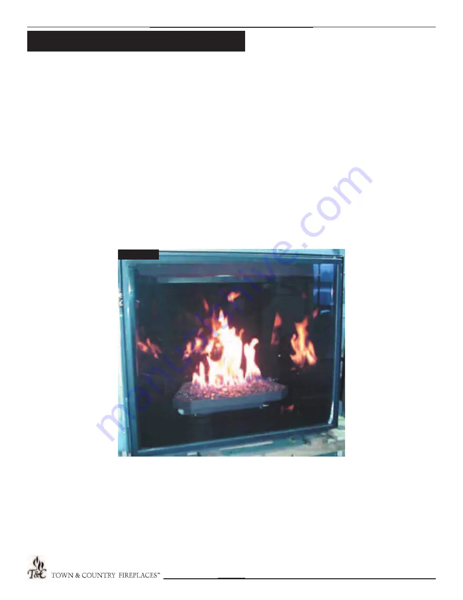
Fig. # 29

The air shutter at the end of the burner inlet tube controls the 
primary combustion air to the gas burner and is preset  closed 
at the factory for natural gas fuel. Shutter must be fully open 
for propane.  See Fig. #29 for proper fl ame pattern.

The fl ame should be just orange and “lazy”.  It should NEVER be set to create 
sooting on internal parts and window glass.

Flame Adjustment

Содержание TC36.NG03.C.

Страница 1: ...l with the appliance CONSUMER Retain this manual for future reference These instructions are supplementary to the Installation and Operating Instructions supplied with the fireplace and should be kept together Refer to the Installation and Operating Instructions for proper gas supply safety requirements and operating instructions ...

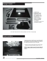
Страница 2: ... BE USED WITH PORCELAIN PANEL SET PART TC36 PNLPBKB A porcelain panel set must be used in conjunction with the installation of the burner assembly See Installation and Operating Instructions manual for details 1 Remove2screwsfromtheairchannelandattachthelower rear panel to the firebox with these screws Fig 1 NOTE The burner shield may need to be loosened and re tightned after positioning if the pa...

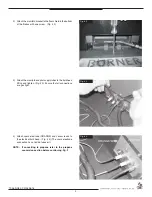
Страница 3: ... pilot supply tubes to the bulk head fitting and tighten Fig 3 Ensure that all connections are gas tight 4 Attach spark electrode ORANGE and sensor leads to the electrical bulk head Fig 4 The spark electrode connection has a red dot above it NOTE If converting to propane refer to the propane conversion section before continuing Pg 9 Fig 3 Fig 2 ...

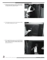
Страница 4: ...ox and tipping the top into position Fig 5 6 Position upper rear panel on top of lower rear panel and slip in behind the right panel Fig 6 7 While supporting the upper rear panel install the left side panel in the same manner as the right side panel Secure both side panels with the previously removed panel retaining clips Fig 7 Fig 6 Fig 7 ...

Страница 5: ...ner shield by tipping the shield into the firebox feed the pilot assembly through the opening in the shield Fig 8 9 Attach pilot shield to burner tray with two screws Fig 9 10 Attachtheburnertraytotheburnershieldusingtwoscrews at the back of the tray Fig 10 ...

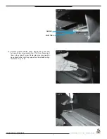
Страница 6: ...stall front and rear media spacers Fig 11 12 12 Install burner by tilting burner inlet through tray Ensure that the orifice has entered the inlet tube Fig 13 14 Set the air shutter to fully open for Propane or fully closed for Natural gas Fig 13 ...

Страница 7: ...ia spacer Secure the spacer and burner with two long screws Fig 15 Four holes must line up to set each screw Some pressure may need to be applied to the front tray support on the shield to align the holes Fig 16 Fig 14 Fig 15 Fig 16 ORIFICE INLET TUBE ...

Страница 8: ...TC36 NG03 C 010408 16 8 Fig 17 14 Apply just enough glass media to cover the burner assembly Fig 17 NOTE Too much glass media over the burner will cause sooting with the use of propane gas ...

Страница 9: ... not proper and complete until the operation of the converted appliance is checked as specified in the manufacturer s instructions supplied with the kit CAUTION The gas supply and electrical power shall be shut off before proceeding with the conversion Note Factory supplied components must be used to ensure correct input After conversion confirm proper manifold pressure 1 Ensure the burner pilot a...

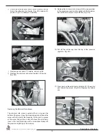
Страница 10: ...t the screw is fully installed Fig 23 10 Pull off the rubber cap from the top of the pressure regulator Fig 24 11 Press down on the center post and rotate 90 The center post should stay down Fig 25 Replace the rubber cap Fig 24 Fig 25 Fig 23 Fig 22 MINIMUM RATE MINIMUM RATE SCREW SCREW Removing the Minimum Rate Screw The minimum rate screw is sealed with an o ring near the bottom of the screw Use ...

Страница 11: ...anifold pressure test port Verify gas pressures with the fireplace lit and on the highest setting 12 Fill in the date and the name of the person who performed the conversion in the white area on the conversion label Peel off the protective backing and apply the conversion label directly over the gas specifications on the rating label 13 Attach the access panel to the side of the firebox with the p...

Страница 12: ...ary combustion air to the gas burner and is preset closed at the factory for natural gas fuel Shutter must be fully open for propane See Fig 29 for proper flame pattern The flame should be just orange and lazy It should NEVER be set to create sooting on internal parts and window glass Flame Adjustment ...

Страница 13: ...9634 7 PILOT SHIELD 9626 002 8 MEDIA SPACER CENTER 9635 9 MEDIA SPACER FRONT 9634 5 ITEM DESCRIPTION PART NO 10 BURNER SHIELD 9636 11 SPRING NUT 5044 12 BURNER TRAY 9632 13 PILOT ASSEMBLY CONVERTIBLE 5005 025 14 1 4 FLEX TUBE 5019 225 15 1 2 FLEX TUBE 5019 223 HARDWARE PACKAGE TC36 HK03 Not sold separately NOTE FIREPLACE VALVE REPLACEMENT PARTS ARE LOCATED IN THE APPLIANCE INSTRUCTIONS Replacement...

Страница 14: ...TC36 NG03 C 010408 16 14 NOTES ...

Страница 15: ...TC36 NG03 C 010408 16 15 NOTES ...

Страница 16: ...TECHNICAL SUPPORT 1 877 715 2664 www townandcountryfireplaces net 2975 Allenby Rd Duncan BC V9L 6V8 Printed in Canada ...

Отзывы: