background image

SM6630 and SM6635 Satellite Modulators 


 36 
 

10 

Recycling 

TANDBERG Television provides assistance to customers and recyclers through 
our web site 

http://www.tandbergtv.com/ProductRecycling.ink

 Please contact 

TANDBERG Television’s customer services for assistance with recycling if this site 
does not show the information you require.   

Where it is not possible to return the product to TANDBERG Television or its 
agents for recycling, the following general information may be of assistance: 

!"

Before attempting disassembly, ensure the product is completely 

disconnected from power and signal connections. 

!"

All major parts are marked or labelled to show their material content. 

!"

Depending on the date of manufacture, this product may contain lead in 

solder. 

!"

Some circuit boards may contain battery-backed memory devices. 


Содержание SM6630

Страница 1: ...ST US E10244 1 ENGLISH UK www tandbergtv com SM6630 and SM6635 Satellite Modulators USER GUIDE SM6630 and SM6635 Satellite Modulators Software Version 1 04 and later ...

Страница 2: ...bergtv com Internet Address http www tandbergtv com Technical Training International Tel 44 0 23 8048 4229 Fax 44 0 23 8048 4467 training tandbergtv com This document and the information contained in it is the property of TANDBERG Television Ltd and may be the subject of patents pending and granted It must not be used for commercial purposes nor copied disclosed reproduced stored in a retrieval sy...

Страница 3: ...p Down 13 2 7 Getting Started 14 3 Operating the Equipment From the Front Panel 15 3 1 Introduction 15 3 2 Booting 15 3 3 Navigating the Menus 16 3 4 Front Panel Interface Modes 17 3 5 Full Access Mode Menu Structure 18 3 6 Using the Full Access Mode 22 4 Preventive Maintenance and Fault finding 25 4 1 Routine Checks 25 4 2 Servicing 25 4 3 Maintenance and Support Services 26 4 4 Maintenance Philo...

Страница 4: ... Panel and Connectors SM6635 model shown which has an L Band output card fitted 9 Figure 2 2 Base Unit Model Signal Connections 11 Figure 3 1 Boot Screen 15 Figure 3 2 Navigation Keys and Buttons 16 Figure 3 3 Front Panel LCD Symbols 16 Figure 3 4 Menu Structure 18 List of Tables Table 1 1 Satellite Modulator Model Descriptions 5 Table 1 2 Software Options 5 Table 2 1 Base Unit Model Connectors 10...

Страница 5: ...VB S2 and PREKOR capable 1 3 Hardware and Software Options There are no hardware options available for the SM6630 and SM6635 Satellite Modulators See Table 1 2 for a list of software options available with the Modulator Detailed information is in the Reference Guide Table 1 2 Software Options Marketing Code Description SM66XX SWO HOM DVB DSNG Higher Order Modulation 8PSK and 16QAM SM66XX SWO 48MSY...

Страница 6: ...bytes the coding bytes are ignored 204 byte packets 188 data bytes and 16 dummy bytes Unframed data i e without MPEG 2 sync bytes When operating in DVB S2 ACM mode the incoming data may only be in BBFRAME format 1 4 3 Transport Stream Rate Adaptation The modulator is capable of performing transport stream rate adaptation with PCR correction allowing it to be used at a fixed symbol rate irrespectiv...

Страница 7: ...d employs a concatenated coding scheme consisting of an outer Bose Chaudhuri Hocquenghem BCH code and an inner Low Density Parity Check LDPC code Each FEC coding scheme provides for a number of different code rates permitting a trade off between bit rate and ruggedness 1 4 8 Modulation Schemes DVB S BPSK and QPSK modulations are available as standard on each base unit model Additionally DVB DSNG 8...

Страница 8: ...e this equipment CAUTION Unauthorised maintenance or the use of non approved replacements may affect the equipment specification and invalidate any warranties 2 2 Operating Voltage The Modulator operates from a wide ranging mains power supply 100 120 Vac or 220 240 Vac 50 60 Hz nominal CAUTION This product should be operated only from the type of power source indicated on the marking label If you ...

Страница 9: ...ore connecting the unit to the supply check the supply requirements in Annex B of the Reference Guide 2 4 Connecting Up the Satellite Modulator 2 4 1 Rear Panel Connectors Always use the specified cables supplied for signal integrity and compliance with EMC requirements see the Reference Guide The connectors used are shown in Figure 2 1 and described in Table 2 1 Figure 2 1 Typical Rear Panel and ...

Страница 10: ...ket provides a beacon receiver input for PREKOR 10 MHz REF IN 50 Ω BNC socket provides a symbol clock reference input BB OUT I 50 Ω BNC socket provides a baseband I channel output BB OUT Q 50 Ω BNC socket provides a baseband Q channel output RS 232 485 A 9 way D type male sub miniature connector provides a control interface which is user configurable as either RS 232 or RS 485 and as either a loca...

Страница 11: ...o be terminated L Band Output Main L Band Output Mon IF Output Main IF Output Mon Baseband I Output Baseband Q Output SM663x Satellite Modulator RS 232 485 RESET STATUS ETHERNET 1 IF OUT MAIN 75R ETHERNET 2 IF OUT MON 75R ASI IN 1 BB OUT I 50R ASI IN 2 BB OUT Q 50R L BAND IN 50R L BAND OUT MAIN 50R L BAND OUT MON 75R BEACON Rx IN 10 MHz REF IN Remote Control Alarm Fail Relay Interface Network Netw...

Страница 12: ...e to isolate the equipment properly may cause a safety hazard Connect the Modulator to the power supply as follows Power Supply Ensure the power supply is isolated and switched off Modulator Ensure the correct fuse type and rating has been fitted to both the equipment and the power cable Supply Cord Connect the lead to the Modulator input connector and then to the power supply Switch on the power ...

Страница 13: ...er up the Modulator by turning on the local mains supply The unit executes a series of power up initialisation and self test routines Ensure that all cooling fans are rotating If they are not switch off the equipment immediately Confirm that the front panel green Power LED is illuminated A warm up period of 60 seconds IF Output models or 5 minutes L Band Output models is required for the internal ...

Страница 14: ...ish local or remote control Connect the relevant terminal to the RS 232 485 port or the Ethernet port 1 or 2 Ensure the terminal is switched on and operational See the Reference Guide for details Section 3 of this Guide gives details of using the Front Panel for day to day operation NOTE The rear panel RS 232 485 connector is compatible with either RS 232 or RS 485 depending upon the mode selected...

Страница 15: ...e front panel For other control methods refer to the Reference Guide NOTE Certain functionality of the Modulator is dependent upon the specific Modulator model the hardware options fitted and the software options installed in it The options available in some front panel and terminal menus vary dependent upon the functionality available and the setting of certain parameters 3 2 Booting NOTE If nece...

Страница 16: ...es made 3 4 5 6 Directional arrow push buttons for navigating LEFT RIGHT UP and DOWN 3 3 2 Screen Symbols The front panel display uses a number of symbols and conventions Figure 3 3 illustrates the use of arrows on the front panel display Table 3 2 describes the symbols and conventions used with the front panel display Figure 3 3 Front Panel LCD Symbols ENTER button CANCEL button Directional arrow...

Страница 17: ...acters use the LEFT and RIGHT arrow push buttons to move to the next digit 3 4 Front Panel Interface Modes There are two front panel user interface modes as follows Monitor Only mode All configuration and log information can be viewed but the user cannot clear logs and cannot save or load configurations Full Access mode In this mode the Modulator can be fully controlled giving the user full access...

Страница 18: ...ll Access mode Logs Menu Configuration Menu System Menu View Status Main View Active Alarms Menu FRONT PANEL MENUS View Alarm Log View Event Log View Temperature Log Clear Alarm Log Clear Event Log Clear Temperature Log Change Parameter Change Configuration View Configuration Load Configuration Save Configuration Edit Config Name Network Settings Network Time Server Serial Port Settings Front Pane...

Страница 19: ... individually Data Select ASI1 ASI2 Null Pkts PRBS Packet Size Unframed 188 bytes 204 bytes Rate Adapt OFF ON Bit Rate 1 84 Mbit s variable limits dependent upon selected Packet Size Modulation FEC Rate and other parameters Symbol Rate 1 5 Msymbol s 0 1 48 Msymbol s with 48 MSym s option or 0 1 66 Msymbol s with 66 MSym s option Standard DVB S DSNG DVB S2 with S2 software option Modulation BPSK QP...

Страница 20: ...with the PREKOR software option Change Configuration Allows changes to the current configuration settings as a block of changes Data Select ASI1 ASI2 Null Pkts PRBS Packet Size Unframed 188 bytes 204 bytes Rate Adapt OFF ON Bit Rate 1 84 Mbit s variable limits dependent upon selected Packet Size Modulation FEC Rate and other parameters Symbol Rate 1 5 Msymbol s 0 1 48 Msymbol s with 48 MSym s opti...

Страница 21: ...Power 20 to 5 dBm IF Output OFF ON Mod State OFF ON IF Spectrum Normal Inverted IF Tilt 0 04 dB MHz to 0 04 dB MHz UpConv Freq 0 000000 100 000000 GHz UpConv Pwr OFF ON available only on model SM6635 UpConv Ref OFF ON available only on model SM6635 DPC State OFF ON available only with the PREKOR software option UFC Mode Manual Automatic available only with the PREKOR software option View Configura...

Страница 22: ... may enter a value for either IF Frequency or Uplink Freq The two parameters are interrelated by either one or other of the following equations dependent upon the setting of IF Spectrum Uplink Freq UpConv Freq IF Frequency IF Spectrum Normal Uplink Freq UpConv Freq IF Frequency IF Spectrum Inverted 3 6 Using the Full Access Mode 3 6 1 Edit Mode Press Enter to expand a selected submenu and to permi...

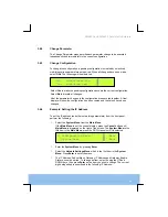
Страница 23: ...hanged 3 6 4 Example Setting the IP Address To set the IP address and other networking parameters from the front panel perform the following Select the System Menu from the Main Menu If the Main Menu is not the current display press the Cancel button until Main Menu is displayed on the right of the screen The System Menu is the fifth item in the Main Menu press the DOWN arrow until it is selected ...

Страница 24: ... to cycle through the characters Use the LEFT and RIGHT keys to navigate along the address When finished press Enter to confirm the change To cancel the change press Cancel NOTE Erroneous address settings cannot be saved IP Addr 192 168 055 003 Edit Mask 255 255 240 000 Mode ...

Страница 25: ...eaners Use a damp cloth for cleaning the exterior of the Modulator 4 2 Servicing 4 2 1 Conditions Requiring Servicing WARNING Do not attempt to service this product as opening or removing covers may expose dangerous voltages or other hazards Refer all servicing to service personnel who have been authorised by TANDBERG Television The following is a list of conditions which may indicate the need for...

Страница 26: ...ition Also performance and EMC checks may be required 4 3 Maintenance and Support Services 4 3 1 Introduction TANDBERG Television is a leader in the design integration and implementation of digital broadcasting products and systems It has a large team dedicated to keeping our customers on air 24 hours a day 365 days a year With regional offices worldwide and ultra modern specialist service facilit...

Страница 27: ...rvice Engineer or contact TANDBERG Television Customer Services see Preliminary Pages WARNING Hazardous voltages are present within this equipment and may be exposed if the covers are removed Only trained AND APPROVED SERVICE Engineers are permitted to service this equipment NOTE Unauthorised maintenance or the use of non approved replacements may invalidate any warranties and or affect the equipm...

Страница 28: ...e carried out 4 5 Alarm and Failure Reporting 4 5 1 Introduction This section describes the alarm and fail conditions which cause the alarm fail relays to be actuated and which are recorded in the Alarm log They are dependent on the cards fitted and in some cases the mode of operation of the Modulator The alarms reported are dependent upon the Alarm Mask settings See the Reference Guide for furthe...

Страница 29: ...r severity level indicates that a service affecting condition has developed and an urgent corrective action is required Such a severity can be reported for example when there is a severe degradation in the capability of the Modulator and its full capability must be restored The critical severity level indicates that a service affecting condition has occurred and an immediate corrective action is r...

Страница 30: ...dows NT 4 0 is recommended For full instructions regarding using FTP refer to the Reference Guide NOTE The Modulator uses a reduced instruction set of standard FTP commands 5 2 Downloading Configurations It is possible to download configurations to the Modulator using FTP Any of the eight stored user configurations config01 cfg to config08 cfg may be changed The currently implemented configuration...

Страница 31: ...r local TANDBERG Television sales representative To obtain a key or keys specify the options required plus the serial numbers of the Modulators These can be obtained from the Terminal or FTP interfaces A single key can enable more than one feature but will only work on a single Modulator When keys are ordered for several Modulators a number of keys may be supplied as a single licence key file 6 3 ...

Страница 32: ...or Ethafoam 220 polyethylene foam inserts can be easily recycled with other low density polyethylene LDPE materials 7 2 Packaging Markings The symbols printed on the outer carton are described below Handle with care This way up Fragile Protect from moisture Defines country of origin See Reference Guide for details of compliance with directives details See Reference Guide for details of compliance ...

Страница 33: ...6635 Satellite Modulators 33 The packaging is reusable per GB 18455 2001 Recyclable per GB 18455 2001 This symbol guarantees that packaging with this symbol is recyclable and will be accepted by cardboard recyclers ...

Страница 34: ...hazardous materials TANDBERG Television expects the normal use environment to be in an equipment room at controlled temperatures around 22 C with moderate humidity around 60 and clean air near sea level not subject to vibration or shock Where TANDBERG Television product contains potentially hazardous materials this is indicated on the product by the appropriate symbol containing the EFUP For TANDB...

Страница 35: ...ons may affect its disposal Regulations policies and or environmental restrictions differ throughout the world Contact your local jurisdiction or local authority for specific advice on disposal 9 2 For the European Union This product is subject to the EU Directive 2002 96 EC on Waste Electrical and Electronic Equipment WEEE and should not be disposed of as unsorted municipal waste ...

Страница 36: ... the information you require Where it is not possible to return the product to TANDBERG Television or its agents for recycling the following general information may be of assistance Before attempting disassembly ensure the product is completely disconnected from power and signal connections All major parts are marked or labelled to show their material content Depending on the date of manufacture t...

Отзывы: