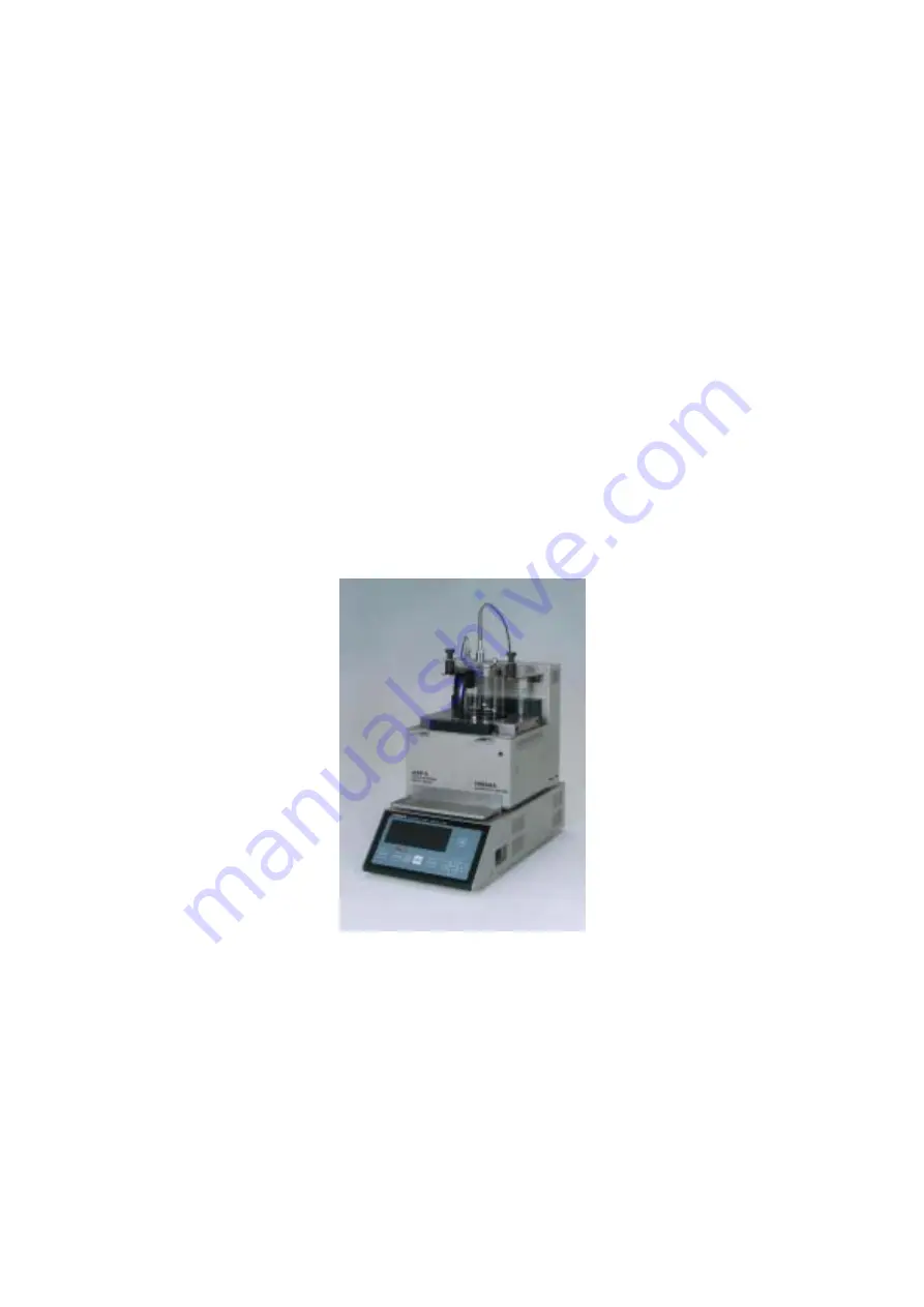
Automated Softening Point Tester
Model ASP-5
Maintenance Manual
Ver.1.10 070913
Read this manual thoroughly before using the product,
and store in a safe place for future reference.
TANAKA SCIENTIFIC LTD, TOKYO, JAPAN
Страница 1: ...ed Softening Point Tester Model ASP 5 Maintenance Manual Ver 1 10 070913 Read this manual thoroughly before using the product and store in a safe place for future reference TANAKA SCIENTIFIC LTD TOKYO...
Страница 2: ...ts Printing 10 2 I O Check 11 3 Adjustment 12 3 1 Ring Holder Adjustment 12 4 Faults and Countermeasures 13 4 1 Fault Displays and Countermeasures 13 4 2 Unit Faults and Countermeasures 16 5 Parts Rep...
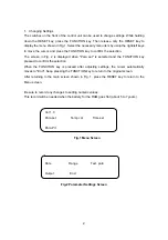
Страница 3: ...set is selected and the FUNCTION key pressed to confirm the selection When the FUNCTION key is pressed after adjusting settings the cursor automatically moves to End Keep pressing the FUNCTION key to...
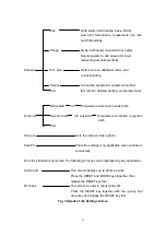
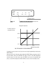
Страница 4: ...correction in water bath Temp cal Glycerin bath C F selection Temperature correction in glycerin bath End Time set Sets the internal clock option Para Prt Prints the settings only applicable when a p...
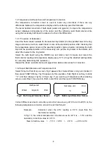
Страница 5: ...ent kinds of bath liquid water and glycerin the following values can be set Liquid Init Base Limit Auto Water 15 50 00 005 C Rise rate P I D 5 0 C min 50 04 60 End Fig 4 Heating Settings Screen Liquid...
Страница 6: ...this is specified tests are performed using the settings from the heating settings screen 1 sample Usually set to off When Yes is specified testing ends after the detection of a one sided drop Cut te...
Страница 7: ...utput Sample drop detection level Fig 7 Sub Screen Add nenu Two additional test modes can be added to the original two test modes To complete testing a sample select On here and also at 1 sample On th...
Страница 8: ...d as an identification number for external connections Test No Counter from 0000 to 9999 incremented by one at the end of each test Opt prt Usually set Off If a printer is connected this setting enabl...
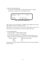
Страница 9: ...t a test Compare and record the thermometer reading and temperature display every 10 C Copy the attached settings table for recording data during this operation Repeat the above operation twice and pi...
Страница 10: ...ath To display the next correction screen move the cursor using the right left keys and press the FUNCTION key When the cursor is at a correction value pressing the FUNCTION key moves the cursor to th...
Страница 11: ...shed move the cursor to End and press the FUNCTION key to return to the previous screen or press the RESET key to return to the standard main screen 1 5 Printing Settings Option If an optional printer...
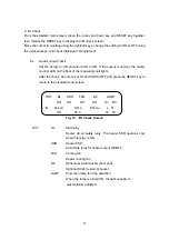
Страница 12: ...of the measuring unit lights After the check be sure to set RL and SSR to OFF and press the RESET key to return to the standard main screen OUT RL SSR FAN BZ LAMP Off Off Off Off On B0 IN Pos err Tem...
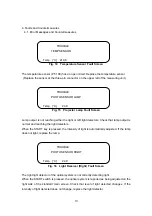
Страница 13: ...13 and tighten the nuts From the top of the ring holder to the lower face of the top plate 100 0 1mm 100 From the lower face of the Ring holder to the upper face of the bottom plate 30 0 1mm 30 Fig 1...
Страница 14: ...ht or left light detectors Check that lamp output is normal and reaching the light detectors When the START key is pressed the intensity of light is automatically adjusted If the lamp does not light r...
Страница 15: ...r Position Incorrect Screen Tests are stopped in about 10 minutes if started without the temperature sensor in place or if the heater has an open circuit Check that the temperature sensor is in place...
Страница 16: ...e sample does not drop within the measuring range In this case press the RESET key and then the FUNCTION key to check the measuring range on the sub screen Circumstances that caused the test to end ca...
Страница 17: ...p not lit The other switches do not work either The other switches work Replace the MAIN board Replace the panel switch sheet The MODE switch does not work The other switches do not work either The ot...
Страница 18: ...the heater SSR Replace the MAIN board The cooling fan does not operate 24VDC is supplied to the fan 24VDC is not supplied to the fan Replace the cooling fan Replace the fan SSR The projection lamp doe...
Страница 19: ...down the wiring arrangement before replacing parts so that the wiring can be reconnected after replacement To remove the control unit cover undo the four screws two on either side and lift the cover u...
Страница 20: ...CN3 Disconnect the power cable from CN1 on the fluorescent display board Remove the four flat head screws from the sides of the panel and detach the panel from the main unit Remove the four screws se...
Страница 21: ...nd point 5 1 White 12 CN1 of the MAIN board 6 1 Green Frame ground Ground point 7 1 Orange AC100V L AC terminal board 8 1 Gray AC100V N AC terminal board 5 2 Measuring Unit Parts Replacements Be sure...
Страница 22: ...at the upper part and detach the case Record the types and order of insulators from the heater terminal board to the heater case Remove two nuts from the heater terminals and detach the heater Put a...
Страница 23: ...its parity check even number parity character code ASCII code start bit 1 bit stop bit 2 bits 2 How to change Baud Rate The factory setting is 1200bps To alter this remove the cover of the control uni...
Страница 24: ...follows Table 2 Pin Assignment Pin Signal Function Direction 1 GND FG Frame Ground 2 TXD SD Transmitting Data Tester Computer 3 RXD RD Receiving Data Computer Tester 4 RTS RS Connect w pin 5 5 CTS CS...
Страница 25: ...ith IBM AT compatible is as illustrated below FG TXD RXD RTS CTS DSR DTR SG 20 2 1 3 4 5 6 7 FG TXD RXD RTS CTS DSR DTR SG 20 2 1 3 4 5 6 7 Tester 25P Computer 25P TXD RXD RTS CTS DSR DTR SG 20 2 3 4...
Страница 26: ...d by character strings The safety shut off temperature was reached or trouble has been found OVER_ 4 letters plus 1 space Reserve Normally this column is blank In case when some trouble has been found...
Страница 27: ...orescent Display Sheet Switch Ferrite Core Ferrite Core 1 2 3 4 ASP 5 Control Unit Wiring Diagram 1 0 Takashi Hori PCB COMMON MAIN XX XX Signal Cable To Test Unit NK2 CN2 FP7 PNL xx xx CN1 CN2 MC1 CM...
Страница 28: ...2 3 4 CN13 5102 04 MULTI MMB 12 02 MPC ASP 2 1 1 Twist 1 2 3 CN1 SCK 1403R Sensor Position Optional Sensor Potision GND Optional V OUT V OUT V OUT V OUT AC L AC N FG CN2 CN1 PS BWS 24SX U OR 0 75 Y 0...