TALOS ITR-CS15D Скачать руководство пользователя страница 16

ITR-CS15D


Chapter 1 

15


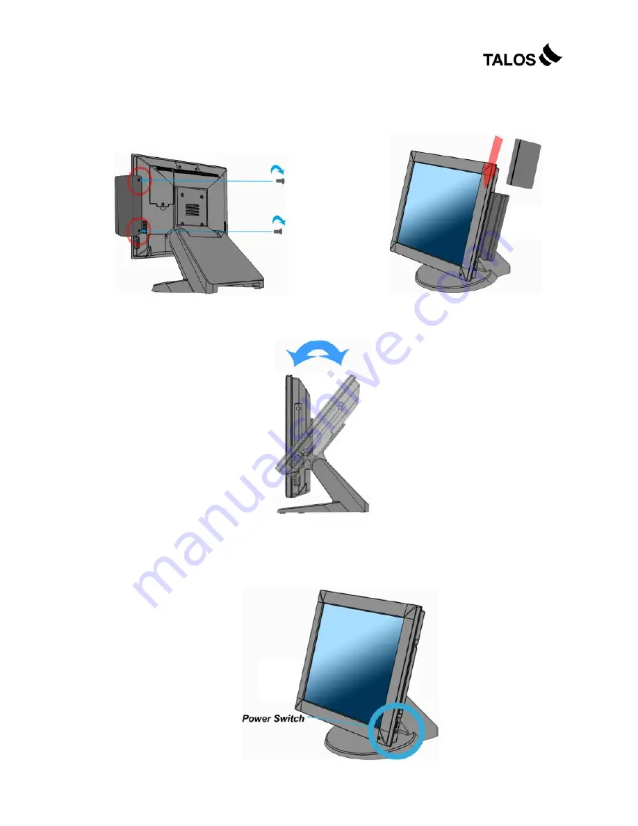
4. Tighten the two M3 screws to fix the MSR 
assembly as shown below. 


5. Finished. 


1.5. Adjust Angle 


1.6. Turn on the device 

1. Make sure all peripherals and cables are connected properly. 
2. Press and hold the power switch until the power indicator on the front panel 

glows green. 


Содержание ITR-CS15D

Страница 1: ...User s Manual ITR CS15D ...

Страница 2: ...r means in any form without prior written permission of the manufacturer All trademarks are property of their respective owners Liability Disclaimer In no event will the manufacturer be liable for direct indirect special incidental or consequential damages arising out of the use or inability to use the product or documentation even if advised of the possibility of such damages Regulatory Informati...

Страница 3: ...SB Keyboard and USB ODD 9 LAN Cable 9 Cash Drawer 9 Customer Display 10 MSR 14 1 5 Adjust Angle 15 1 6 Turn on the device 15 2 Basic Driver Installation 16 2 1 Before the installation 16 2 2 Chipset Software Installation 16 2 3 VGA Driver Installation 17 2 4 Touch Screen Driver and Software Utility installation 18 2 5 LAN Driver Installation 20 3 Touchscreen Control Panel Quick Guide 23 3 1 Launch...

Страница 4: ...ITR CS15D Contents iii 4 2 Serial Port COM1 3 35 4 3 COM 2 10 Pin RJ50 35 4 4 Cash Drawer 36 5 Specification 37 ...

Страница 5: ...TR CS15D Chapter 1 4 1 1 Hardware Setup 1 1 Packing Contents 1 ITR CS15D X 1 4 RJ50 to DB9 COM port adapter cable X 1 2 Power Adapter X 1 5 IO Cable Cover X 1 3 Power Cord X 1 6 Drive and Utility DVD X 1 ...

Страница 6: ...k Tour Front View and Side View A The LED indicator will glow green when power is on The LED indicator will blink red when the HDD is accessed A Customer Display mounting hole cover D Power switch B HDD tray E I O cover C MSR cover ...

Страница 7: ...M 2 10 pin RJ 50 H CF card slot C USB 1 2 I USB 3 4 D LAN 1 J COM3 E LAN 2 K VGA F COM1 CAUTION Note Please use 10 pin RJ50 connector 8 pin RJ45 is incompatible 1 3 HDD Replacement 1 Loosen and remove the screws fixing the HDD tray 2 Pull out the HDD tray slightly and softly ...

Страница 8: ...7 3 Disconnect the SATA cable connector and the SATA power cable connector 4 Loosen and remove the four screws fixing the HDD and then remove the HDD from the HDD tray 5 Install the new HDD onto the device in reverse order ...

Страница 9: ...over from the device 2 All cables and wires from peripherals to the POS device are recommended to be fed through the base in the direction as shown below WARNING Before the cable cover is removed please make sure the power is off Power Adapter Connect the DC cable to the DC in jack ...

Страница 10: ...USB 1 2 or UBS 3 4 ports on the back panel of the device LAN Cable Connect one end of RJ 45 LAN cable to the LAN 1 or LAN 2 port on the back panel of the device another end to your internet device Cash Drawer Connect one end of RJ 11 cable to the Cash Drawer port on the back panel of the device another end to your cash drawer ...

Страница 11: ...el cove Customer Display A Hardware Installation 1 Remove the two screws and the VFD mounting hole cover from the device and then pull out the connector from the device 2 Adjust the hinge of the VFD and then connect to the device as shown below ...

Страница 12: ...he DEL key to enter the BIOS When the BIOS screen appears use the or key on your external computer keyboard to select Advanced Use the arrow keys of the external keyboard to select IO Configuration and then press the ENTER key WARNING Never enable the 12V power without the customer display attached and be sure to disable the 12V power before removing the customer display ...

Страница 13: ...ITR CS15D Chapter 1 12 2 The screen below will appear Use the or key to scroll the screen and highlight the COM6 RI 12V 15V and then press the Enter key 3 Highlight 12V and then press the Enter key ...

Страница 14: ...TILITY screen of step 1 use the or key on your external computer keyboard to select the EXIT Use the or key to highlight Save Changes and Exit 5 Press the Enter key use the or key to highlight the Ok press the Enter key again to save your voltage configuration and exit BIOS ...

Страница 15: ...ITR CS15D Chapter 1 14 MSR 1 Remove the two screws fixing the MSR cover 2 Remove the MSR cover from the device 3 Connect the connectors of the MSR assembly to the device ...

Страница 16: ...rews to fix the MSR assembly as shown below 5 Finished 1 5 Adjust Angle 1 6 Turn on the device 1 Make sure all peripherals and cables are connected properly 2 Press and hold the power switch until the power indicator on the front panel glows green ...

Страница 17: ...l USB CDROM to the USB power and insert the driver CD and turn on the device The program autoruns and displays the Talos Integrated Technologies main screen 2 2 Chipset Software Installation 1 On the main screen click INTEL Chipset Driver 2 Click Next 3 Read the License Agreement carefully and clic Yes ...

Страница 18: ...17 4 Click Next 5 Click Finish 2 3 VGA Driver Installation 1 On the main screen click VGA Driver 2 Click the operation system according to your application 3 Click Next 4 Read the License Agreement carefully and click Yes ...

Страница 19: ...ick Next 7 Select restart your computer right now or later and then lick Finish 2 4 Touch Screen Driver and Software Utility installation 1 On the main screen click Touch Panel Driver 2 Click the operation system according to your application ...

Страница 20: ...edure starts 4 Click Next 5 Check the Install PS 2 interface driver box and click Next 6 Select an item according to your needs and then click Next 7 Click OK 8 If you want to use Multi Monitor check the box and click Next 9 Click Next ...

Страница 21: ...15D Chapter 2 20 10 Click Next 11 The driver starts to install 11 Click OK 2 5 LAN Driver Installation 1 On the main screen click VIA 6130 LAN Drive 2 Click the operation system according to your application ...

Страница 22: ...driver will be installed automatically 4 Click OK on the pop up message box 2 6 Audio Driver Installation 1 On the main screen click HD Audio Driver 2 The driver is preparing to install 3 Click Next 4 Select I Agree and click Next ...

Страница 23: ...ITR CS15D Chapter 2 22 5 Check VIA HD Audio Codec Drive v7 300 30 090715 box and then click Next 6 Click Next 7 Click Next 8 Select restart your computer right now or later and then lick Finish ...

Страница 24: ... Guide 3 1 Launch TouchKit Utility There are two alternatives to launch TouchKit Option 1 Under Microsoft Windows XP click start menu and select Programs under TouchKit menu click Configure Utility Option 2 Click icon on the task bar to launch TouchKit utility ...

Страница 25: ...al controller icon object will be shown in the controller list window automatically USB TouchKit device supports plug and play the icon object for USB controller will be shown in the controller list window automatically when the USB controller is connected with the USB port of the device And the icon object for the USB controller will disappear automatically as soon as the device was removed from ...

Страница 26: ...tically USB TouchKit device supports plug and play the icon object for USB controller will be shown in the controller list window automatically when the USB controller is connected with the USB port of the device And the icon object for the USB controller will disappear automatically as soon as the device was removed from the system USB port TouchKit utility does not allow you to remove uninstall ...

Страница 27: ...ol the beep sound frequency generated by the driver Duration Drag the slider to adjust this duration to control the beep sound duration Linearization Style TouchKit utility provides you with both 9 points and 25 points calibration for linearization You can select the suitable linearization type Double Click Time Double Click Time is used to set double click time Change this value will affects the ...

Страница 28: ... and dragging the object Click On Touch With this Click On Touch mode the driver emulates a mouse click event when the touchscreen state was switched from un touched state to touched state Then the driver always generate mouse move event and is tracking the touch position until the touchscreen state switched to un touch state Click On Release With this Click On Release mode the driver emulates a m...

Страница 29: ...does not move to the touch position except the lift off point Option You can set configuration for some advanced functions with this option button Press this button a pop up property sheet window will be popped up and shown as below 3 4 Tools There are function buttons and check boxes in the Tools tab ...

Страница 30: ...e one of three these buttons and follow the instruction on the screen to do the screen calibration Draw Test After clicking this button you can do the drawing test by drawing any path on the screen as shown below You can remove all paths you drew by clicking Clear or exit this screen by clicking Quit ...

Страница 31: ... multiple monitor Check this check box to enable multiple monitor support and uncheck it to disable multiple monitor support When this function is disabled the touchscreen will be mapped to the primary monitor automatically When this function is enabled user can double click on the monitor area in the monitor geometry window to assign the monitor area where the touchscreen will be mapped In other ...

Страница 32: ...ther monitor mapping and multiple monitor function enabled Operation Mode TouchKit driver support split display mode for those applications which do not map the touchscreen to the full screen of the monitor Full screen The touchscreen will be mapped to the full screen of the specified monitor Right screen The touchscreen will be mapped to the right half screen of the specified monitor Left screen ...

Страница 33: ...rter 4 The touchscreen will be mapped to the 4th quarter area of the specified monitor display Customized If the touchscreen needs to be mapped the area other than the above area user can define the mapping area for application With this mode the driver does not correct the mapping area when the display resolution changed It needs to do configuration setting again whenever the display resolution c...

Страница 34: ...ottom edge Left If you set the Edge to Smaller TouchKit will reduce the vertical position of the right edge If you set the Edge to Larger TouchKit will extend the vertical position of the left edge Right If you set the Edge to Smaller TouchKit will reduce the vertical position of the right edge If you set the Edge to Larger TouchKit will extend the vertical position of the right edge In some cases...

Страница 35: ...e this function from left corner Edge Compensation Button Click 10 or 10 button to adjust the smaller or larger of edge If you click 10 button the top bottom left and right edges will extend 10 of orientation to touch screen and cursor will be moved 10 pixel of X and Y Axis to right and top If you click 10 button the top bottom left and right edges will contract 10 of orientation to touch screen a...

Страница 36: ...ings 4 1 Power Connector PIN Description PIN Description 1 19V 3 GROUND 2 19V 4 GROUND 4 2 Serial Port COM1 3 PIN Description PIN Description 1 DCD 6 DSR 2 RXD 7 RTS 3 TXD 8 CTS 4 DTR 9 RI 5V 12V 5 GND 4 3 COM 2 10 Pin RJ50 PIN Description PIN Description 1 RI 5V 12V 6 RX 2 DSR 7 GND 3 RTS 8 CTS 4 GND 9 DTR 5 TX 10 DCD ...

Страница 37: ...ter 5 36 4 4 Cash Drawer Connector PIN Description PIN Description 1 GND 4 P24V 2 D_OUT0 5 D_OUT1 3 D_IN 6 GND Cash Drawer Control Status Address Value Open 280H Bit 4 0 Close 280H Bit 4 1 Read Status 281H Bit 0 0 1 ...

Страница 38: ...ITR CS15D Chapter 5 37 5 5 Specification ...

Страница 39: ...232 422 485 DB 9 COM 2 RS232 RJ50 10 pins COM 3 RS232 DB 9 COM 4 RS232 Internal pin header COM 5 RS232 Internal 15 Pin header with PS 2 COM 6 RS232 Internal pin header for Customer Display VGA 1 x VGA USB 4 x USB 2 0 LAN 2 x Gigabit Ethernet by RJ 45 Support Wake on LAN Cash Drawer 1 x RJ 11 Power Pin 24V Others Wall mount Support VESA Mount Power Input External adapter 135W 19VDC input Color Blac...

Страница 40: ...lay VFD Attached 20 columns x 2 lines RS 232 Type MSR Front Type 3 Tracks PS 2 Type MSR Side Type 3 Tracks PS 2 Type Finger Print USB Type MSR Side Type 3 Tracks PS 2 Type i Button PS 2 Type 12 1 2nd Display Specifications are subject to change without notice ...

Отзывы: