6
7
APPLICATION CONDITIONS
AU
AU
This log splitter is a home use model. It is designed for operating under ambient temperatures
b5
˚
C and 40
˚
C and for installation at altitudes no more than 1000m above M.S.L. The sur-
rounding humidity should be less than 50% at 40
˚
C. It can be stored or transported under ambient
temperatures between -25
˚
C and 55
˚
C.
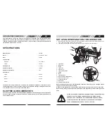
SPECIFICATIONS
Model Number
. . . . . . . . . . . . . . . . . . . . . . . . . . . . . . . . . . . . . . . . . . . . . . . . . . .FB4052
Motor
. . . . . . . . . . . . . . . . . . . . . . . . . . . . . . . . . . . . . . . . . . . . . . . . . . . . . . . . . .240V~50Hz ,IP54
Input
. . . . . . . . . . . . . . . . . . . . . . . . . . . . . . . . . . . . . . . . . . . . . . . . . . . . . . . . . . .1500W
Log Capacity
Diameter * . . . . . . . . . . . . . . . . . . . . . . . . . . . . . . . . . . . . . . . . . . . . . . . . . . . .50~ 250mm
Length . . . . . . . . . . . . . . . . . . . . . . . . . . . . . . . . . . . . . . . . . . . . . . . . . . . . . . .520mm
Splitting Force
. . . . . . . . . . . . . . . . . . . . . . . . . . . . . . . . . . . . . . . . . . . . . . . . . .4 tonnes
Hydraulic Pressure
. . . . . . . . . . . . . . . . . . . . . . . . . . . . . . . . . . . . . . . . . . . . . . .16Mpa
Hydraulic Oil Capacity
. . . . . . . . . . . . . . . . . . . . . . . . . . . . . . . . . . . . . . . . . . . .3.5L
Overall Size
Length . . . . . . . . . . . . . . . . . . . . . . . . . . . . . . . . . . . . . . . . . . . . . . . . . . . . . . .940mm
Width . . . . . . . . . . . . . . . . . . . . . . . . . . . . . . . . . . . . . . . . . . . . . . . . . . . . . . . .270mm
Height . . . . . . . . . . . . . . . . . . . . . . . . . . . . . . . . . . . . . . . . . . . . . . . . . . . . . . . .510mm
Weight . . . . . . . . . . . . . . . . . . . . . . . . . . . . . . . . . . . . . . . . . . . . . . . . . . . . . . .42kg
The diameter of the log is indicative - a small log can be difficult to split when it has knobs or a par-
ticularly tough fiber. On the other hand, it may not be difficult to split logs with regular fibers even
if its diameter exceeds the max. figure indicated above.
ELECTRICAL REQUIREMENTS
Connect the main leads to a standard 240V±10% (50Hz±1Hz) electrical supply which has protection
devices of under-voltage, over-current as well as a residual current device (RCD) which maximum
current rated at 0.03A.
1.
Log Pusher
2.
Work Table
3.
Wedge
4.
Lift Handle
5.
Support Leg
6.
Log Retaining Plates
7.
Switch
8.
Motor
9.
Pushbutton Box
10. Wheels for Minor Moving ONLY.
11. Hydraulic Control Lever
12. Control Lever Guard
13. Bleed Screw
14. Oil Drain Bolt w/ Dipstick
12
2
3
10
4
SET UP AND PREPARATION FOR OPERATION
1. Bolt the Support Leg to the Log Splitter, lift the log splitter by the handles at both ends and place it on
a 60 - 75cm high, stable, flat and level work surface.
2. Familiarize yourself with the controls and features of this log splitter in the illustrations.
11
5
7
8
9
1
Before operating the log splitter, the Bleed Screw should be loosened by some rotations until air
can go in and out of the oil tank smoothly.
Air flow thru the Bleed Screw hole should be detectable while the log splitter is under operations.
Before moving the log splitter, make sure the Bleed Screw is tightened to avoid oil leaking from this
point.
6
FAILURE TO LOOSEN THE BLEED SCREW WILL KEEP THE SEALED AIR IN
HYDRAULIC SYSTEM BEING COMPRESSED AFTER BEING DECOM-
PRESSED. SUCH CONTINUOUS AIR COMPRESSION AND DECOMPRES-
SION WILL BLOW OUT THE SEALS OF THE HYDRAULIC SYSTEM AND
CAUSE PERMANENT DAMAGE TO THE LOG SPLITTER.
14
13
Содержание FB4052
Страница 7: ...12 AU PARTS SCHEMATIC ...


