background image

TS-8807PP 

Wireless Microphone

15

Receiver:

Receiver Power Supply: DC 12V    0.5A
Wireless Connector: TNC/Impedance 50 Ohm
Receiver Sensitivity: ≤-85±5dBm (test after connection)
Max Audio Output: 2V/RMS(at 1KHz  THD=1%)
Audio Output: independent(XLR)and combo(6.3mm)
Receiver Dimension (L*W*H): 430*190*51mm
Net Weight: 2360g
Note: The above data is measured by Takstar laboratory, and Takstar has the 
final interpretation right!

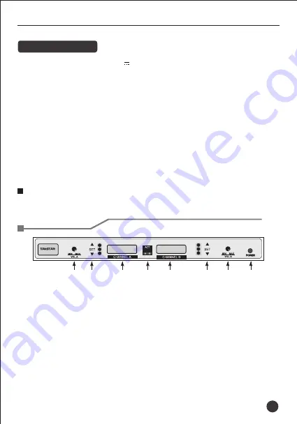
① Volume control: it adjusts the output volume. 
② LCD: It displays matching status, frequency and the receiving signal level. 
③ Infrared matching window: It is used with SET button to transmit the 
      frequency parameter to the transmitter. 
④ Power switch: It turns on/off the receiver. When the receiver is turned on, 
     LCD lights up. 
⑤ Function button: it is used for frequency adjusting, matching and 
      scanning.

Function Instruction

Receiver
Front panel:

TS-8807PP

Содержание TS-8807PP

Страница 1: ...Wireless Microphone TS 8807PP User Manual V2 0...

Страница 2: ...TS 8807PP 400 6828 333 ID SQ XLR 6 3 5 1 TS 8807PP...

Страница 3: ...960 MHz 200 50MHz 250KHz 25KHz FM ID 48KHz 80Hz 16KHz 0 015 100dB A 90dB A 0 5 at 1KHz 50 DC 12V 0 5A TNC 50 85 5dBm 2V RMS at 1KHz THD 1 XLR 6 3mm L W H 430 190 51mm 2360g 2 AA 10mW 8 LxWxH 100x64x2...

Страница 4: ...TS 8807PP SET 8 8 FREQ MUTE 6 A B 3 TS 8807PP...

Страница 5: ...12V DC 0 40dBm XLR P SET SET 2 4 8 MIC MIC 5 TS 8807PP 4...

Страница 6: ...ON 150Hz OFF 3 5mm 1 4 0 8 4 A CHA B CHB 1 2 5 A 2 MIC B TS 8807PP 5...

Страница 7: ...1 C 2 90 D TS 8807PP 6...

Страница 8: ...250 5 658 550 665 950 5 641 950 666 750 6 652 450 680 050 6 659 450 667 950 6 646 300 672 350 7 653 050 688 550 7 660 650 665 000 7 646 900 677 350 8 653 450 681 700 8 661 200 675 850 8 649 000 680 10...

Страница 9: ...TS 8807PP 3 RF AF SET 3 SET 3 1 IR ACT 10cm 50cm SET SET 2 3 IR ACT 8...

Страница 10: ...TS 8807PP 3 3 250KHz SET 250KHz 25KHz SET 25KHz 9...

Страница 11: ...TS 8807PP 1 2 3 4 5 6 7 8 10...

Страница 12: ...0 5m 5 15CM TS 8807PP 11...

Страница 13: ...TS 8807PP 12...

Страница 14: ...eceiver has the function of one button to automatically scan and quickly select the channel without interference One key infrared auto sync between transmitter and receiver The receiver has SQ adjusti...

Страница 15: ...tity dual channels Signal Channel 200 FM width 50MHz Channel Spacing 250KHz or 25KHz Modulation Demodulation FM Mute Control pilot frequency ID code Modulation Deviation 48KHz Frequency Response 80Hz...

Страница 16: ...data is measured by Takstar laboratory and Takstar has the nal interpretation right Volume control it adjusts the output volume LCD It displays matching status frequency and the receiving signal leve...

Страница 17: ...urrent operation frequency Mute display when MUTE lights up this means the receiver is in mute status 6 character display it displays the current information Channel selection display is channel A is...

Страница 18: ...Mode press button to increase MIC Gain button in Gain Adjustment Mode press button to decrease MIC Gain Power button keep pressing the Power Switch 2 seconds to turn On O and press it shortly to turn...

Страница 19: ...clip used to pack the transmitter on the waist belt Mic connector used to link with mic of 3 5mm connector External antenna 1 4 wave length antenna to increase the signal transmission range 18 Gain ra...

Страница 20: ...ton and take out the compartment Load two AA batteries in the compartment according to correct polarity Push the battery compartment in fully Refer to the gure A below 2 Connect the headset mic or lav...

Страница 21: ...ect the external antenna with the antenna connector of receiver and turn it clockwise fully Refer to gure C below 2 Put the side marked with frequency of antenna upward Fold the antenna to form a 90 a...

Страница 22: ...locked power switch excluded Unclock press SET button for 3 seconds for unlocking and it displays the interface refer to gure Frequency adjustment 1 Adjusting frequency manually Refer to gure shortly...

Страница 23: ...turn on the transmitter Point IR window to AC Note when multiple units are used the matched transmitter needs to turned on and then the system will scan the next receiver 3 Adjusting channel interval...

Страница 24: ...receiver front panel is facing to the operation direction or the receiver is kept in the metal box put the antenna to the front panel for better receiving e ect During operation if the LCD screen of t...

Отзывы: