de
it
pt
fr
es
en
nl
19
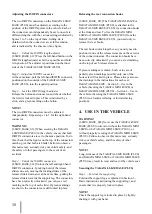
Step 2 – Place on the vehicle seat
[I-SIZE_BASE_016] Place the TAKATA I-SIZE
BASE (PLUS) on the seat of the vehicle. Ensure that:
• The ISOFIX connectors are pointing to the back of
the car seat.
• The support leg is pointing to the vehicle
fl
oor.
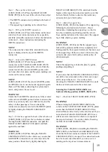
Step 3 – Pull out the ISOFIX connectors
[I-SIZE_BASE_012] Press in the button on the inner
side of each rear connection arm as far as possible,
and fully extend the connectors. Follow the instruction
in Section 3 – Basic instructions (Adjusting the
ISOFIX connectors).
NOTE!
The connectors have been fully extended when no
fi
gure is displayed on the top of the ISOFIX
connectors.
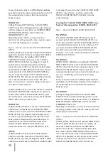
Step 4 – Connect the ISOFIX system
[I-SIZE_BASE_017] Point the open ISOFIX
connectors on the TAKATA I-SIZE BASE (PLUS)
towards the ISOFIX points of the vehicle. Slide the
connectors into the vehicle’s ISOFIX points, until
each one clicks into place, and the green markings are
visible on the release sliders.
NOTE!
[I-SIZE_BASE_018] If the vehicle’s ISOFIX points
are dif
fi
cult to reach, use the feeder supplied to guide
them out. This makes connecting the system much
easier, and protects the seat cover.
WARNING!
Ensure that both ISOFIX connectors are fully secured
to the vehicle’s ISOFIX points. Failure to observe this
notice may seriously risk your child’s safety, and the
safety of other passengers. You can check the
connectors are properly secured to the ISOFIX points,
by lightly shaking the TAKATA I-SIZE BASE
(PLUS).
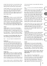
Step 5 – Fit the base against the back of the vehicle seat
[I-SIZE_BASE_019] Press the two buttons to adjust
the length of the ISOFIX connectors, and push the
TAKATA I-SIZE BASE (PLUS) until it sits
fl
ush
against the seat back.
WARNING!
[I-SIZE_BASE_020] When
fi
xing the TAKATA
I-SIZE BASE (PLUS) to the vehicle seat, ensure that
both ISOFIX connectors are set correctly and to the
same position. Check this by lightly shaking the
TAKATA I-SIZE BASE (PLUS), and check that the
fi
gures on the top of the connectors match up (or that
both are blank). Failure to observe this notice may
seriously risk your child’s safety.
Step 6 – Adjust the support leg
[I-SIZE_BASE_022] Set the height of the support leg,
following the instructions in Section 3 – Basic
instructions (Adjusting the support leg), so that its
base lies completely and
fl
ush against the vehicle
fl
oor, and the indicator at the lower end of the support
leg is fully showing a green marking.
WARNING!
[I-SIZE_BASE_022] Ensure that the support leg is
locked into position, and that it lies completely and
fl
ush against the
fl
oor (green indicator at the lower end
of the support leg). Failure to observe this notice may
seriously risk your child’s safety, and the safety of
other passengers.
NOTE!
Check the support leg is locked in place by gently
pushing and pulling it.
NOTE!
If you notice that the TAKATA I-SIZE BASE (PLUS)
can still be moved around on the vehicle seat, repeat
all the steps in Section 4 – Use in the vehicle
(Securing the TAKATA I-SIZE BASE (PLUS)), until
the base is
fi
rmly secured to the vehicle seat.
Securing the TAKATA MINI I-SIZE in a
backward-facing position [I-SIZE_BASE_023]
Step 1 – Check the TAKATA I-SIZE BASE (PLUS)
WARNING!
When securing the TAKATA MINI I-SIZE in the
vehicle on the TAKATA I-SIZE BASE (PLUS), please
ensure that the TAKATA I-SIZE BASE (PLUS) is
attached
fi
rmly and correctly to the vehicle seat. If you
notice that the TAKATA I-SIZE BASE (PLUS) can
still be moved around on the vehicle seat, repeat all
the steps in Section 4 – Use in the vehicle (Securing
the TAKATA I-SIZE BASE (PLUS)).
WARNING!
[I-SIZE_BASE_024] Before installing the TAKATA
MINI I-SIZE on the TAKATA I-SIZE BASE (PLUS),
check that both rear connection hooks of the TAKATA
I-SIZE BASE (PLUS) are open. The connection hooks
have been correctly unlocked if you can see a red
marking on the top of each release element.
en

