


Installation
9
│
Page
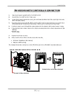
The
dark
squares
indicate
the
direction
the
dipswitches
should
be
set
to.
Left
bank
of
dipswitches
Left
bank
of
dipswitches
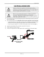
•
There
is
a
3”
clearance
from
the
left
and
right
sides
of
the
unit
to
combustible
and
non
‐
combustible
surfaces.
However,
if
any
portion
or
area
of
the
surface
is
exposed
to
the
exhaust
fumes
(i.e.
directly
to
the
sides
of
the
vent
cap),
that
surface
must
be
at
least
24”
away.
•
Keep
the
clearances.
2,500 to
4,000 ft 4,000
to
5,000
ft
Altitude
HIGH
‐
ALTITUDE
INSTALLATIONS
Check
the
elevation
where
your
water
heater
is
installed.
Set
dipswitches
shown
in
the
table
below
depending
on
the
altitude.
These
dipswitches
(No.
5
and
No.
6)
are
on
the
computer
board
on
the
left
bank
only.
0
to
2,500
ft
(DEFAULT)
Over
5,000
ft
Switch
No.5
OFF
ON
OFF
Consult
TAKAGI
Technical
Dept.
at
1
‐
888
‐
882
‐
5244
Switch
No.6
OFF
OFF
ON
T
‐
H2
‐
OS
INSTALLATION
1.
Install
the
T
‐
H2
‐
OS
only
in
areas
with
mild,
temperate
climates.
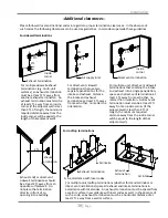
2.
The
T
‐
H2
‐
OS
shall
be
wall
‐
mounted
or
mounted
on
a
stand.
Locate
the
T
‐
H2
‐
OS
in
an
open,
unroofed
area
and
maintain
the
following
minimum
clearances:
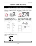
DO
NOT
adjust
any
dipswitches
on
the
right
bank
.
1
2
3
4
5
6
7
8
N O
9
1
0
N O
1
2
3
4
5
6
7
8
9
1
0
N O
1
2
3
4
5
6
7
8
9
1
0
Side
3”
Top
36”
Side
3”
Front
24”
Bottom
12”
Back
0.5”


