


© TAKACAT GmbH - Friedel Hacker (Dipl.-Ing.)
Page
5
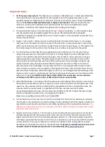
Step 6:
Models with side floor bow tip fixation:
Remove the high pressure floor and place it snugly between the
support tubes and the transom area. Ensure that the middle bottom end tab is between the transom plate
and the high pressure floor. Inflate the
high pressure floor to at least 600 mbar
(max. 689 mbar) and make
sure that it is correctly seated and positioned between the support hoses. At the end of the pumping
process, close the valves with the corresponding protective covers. Finally, lash the bow tips to the high-
pressure bottom using the supplied straps and the corresponding eyelets.
You can find an illustrative video under:
https://www.youtube.com/watch?v=fO7p9GyMDck
Models with central floor bow point fixation:
Place the high pressure floor between the driving hoses. The
correct position is achieved when the two fixing rings can be inserted at right angles through the two slots
of the connecting floor. Pump up the
high pressure floor to at least 600 mbar
(max. 689 mbar) and make
sure that the floor is correctly seated and positioned between the driving hoses. At the end of the pumping
process, close the valves with the corresponding protective covers. Connect the two fixing rings with a rope
or one of the enclosed lashing straps.
You can find a video illustration at:
https://www.youtube.com/watch?v=hg5OCl94GFc
Always ensure that the valve adapter is correctly locked and keep a proper distance during the pumping
process so that no injuries are caused if the air hose should jump off!
Step 7:
Push the individual parts of the two oars together correctly until the locking heads are clearly visible and fix
the two oars with the appropriate screw and Velcro fastener as shown in the pictures above.
Step 8:
The optional fishing rod holders are inserted from the inside into the left and right receptacles of the upper
transom mount until the locking heads indicate the correct position, see illustration in step 5.
Step 9 (only applies to open transom):
The optional wheels are inserted into the corresponding brackets on the left and right side of the lower
transom mount. The correct position is when the wheels are on the inside.
The wheels must not be
positioned under the tubes, otherwise the tubes will be damaged
The slip wheels are only designed for
boat weights and for the slip proccess only.
Step 10:
If you are installing an outboard (short shaft only) then please make sure that the outboard is correctly
positioned on the transom plate. The pressure plates of the toggle screw connection must not press into
the transom rod. If necessary a spacer must be placed underneath (only applies to open transom). Please
observe the instructions and safety regulations of the outboard manufacturer.
The Takacats are designed for
outboards with short shaft. Outboards with long shaft or extra long shaft must not be used.
Step 11:
The seat supplied is inflated to 200mbar and positioned in the boat as required. At the end of the pumping
process, close the valves with the corresponding protective covers.
Always make sure that the valve adapter
is correctly locked and keep a proper distance during the pumping process so that no injuries are caused if
the air hose should jump off!
Dismantling
Dismantling and removal of the boat is done in reverse order.
Step 1:
Loosen the fixation of the high pressure floor on the underside of the bow. Open the protective cap of the
high pressure bottom valve and set the valve pin to the "deflate" position. Then remove the high pressure
bottom and roll it up in the direction of the valve.