


170
Power Supply Fault Finding
TM8100/TM8200 Service Manual
© Tait Electronics Limited
June 2006
Task 5 —
Check Power-up
Options
The functioning of the power-up options may be checked as described in
below. Carry out the procedure in the appropriate step or
steps. In all four cases the procedure involves checking the digital power-up
signal at pin 5 of IC602. For a particular option, the activation mechanism
is the condition that results in the power-up signal becoming active (the
signal is active high).
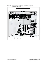
1.
For the battery power-sense option the link
LK1
should be inserted
(see
). Check the power-up signal at pin 5 of
IC602
(see
) while first disconnecting and then reconnecting the
13.8V DC supply at the power connector.
The power-up signal should go high when the power is reconnected.
If it does, conclude with
. If it does not, check for continuity
and shorts to ground between the link
LK1
and the
+13
V
8
BATT
input
at the power connector
PL100
. Repair any fault and go to
.
2.
For the auxiliary power-sense option the link
LK2
should be inserted
(see
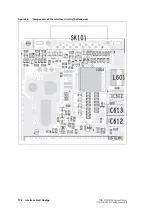
). C3.3V DC (more than 2.6V to be
precise) from the power supply to the
AUX GPI
3
line (pin 4 of the
auxiliary connector
SK101
). Check that the power-up signal at pin 5
of
IC602
(see
) is high.
Remove the +3.3V supply and ground the
AUX GPI
3
line (to be precise
the voltage on the line should be less than 0.6V). If the power-up
signal is now low, conclude with
. If it is not, check for
continuity and shorts to ground between
D601
(see
) and
pin 4 of the auxiliary connector
SK101
. Repair any fault and go to
3.
For the emergency power-sense option the link
LK3
should be
inserted (see
). Connect the
AUX GPI
2
line (pin 5 of the
auxiliary connector
SK101
) to ground. Check that the power-up
signal at pin 5 of
IC602
(see
) is high.
Remove the connection to ground. If the power-up signal is now
low, conclude with
. If it is not, check for continuity and shorts
to ground in the path from
D601
(see
Q600
(see
), to pin 5 of the auxiliary connector
SK101
. Repair
any fault and go to
.
Содержание TM8235
Страница 1: ...TM8100 mobiles TM8200 mobiles Service Manual MMA 00005 04 Issue 4 June 2006...
Страница 10: ...10 TM8100 TM8200 Service Manual Tait Electronics Limited June 2006...
Страница 62: ...62 Description TM8100 TM8200 Service Manual Tait Electronics Limited June 2006...
Страница 148: ...148 Disassembly and Reassembly TM8100 TM8200 Service Manual Tait Electronics Limited June 2006...
Страница 162: ...162 Servicing Procedures TM8100 TM8200 Service Manual Tait Electronics Limited June 2006...
Страница 178: ...178 Interface Fault Finding TM8100 TM8200 Service Manual Tait Electronics Limited June 2006...
Страница 258: ...258 Receiver Fault Finding TM8100 TM8200 Service Manual Tait Electronics Limited June 2006...
Страница 380: ...380 Transmitter Fault Finding 25W TM8100 TM8200 Service Manual Tait Electronics Limited June 2006...
Страница 404: ...404 CODEC and Audio Fault Finding TM8100 TM8200 Service Manual Tait Electronics Limited June 2006...
Страница 428: ...428 Fault Finding of Control Head with Graphical Display TM8100 TM8200 Service Manual Tait Electronics Limited June 2006...
Страница 446: ...446 Spare Parts TM8100 TM8200 Service Manual Tait Electronics Limited June 2006...
Страница 447: ...TM8100 TM8200 Service Manual 447 Tait Electronics Limited June 2006 TM8100 mobiles TM8200 mobiles Chapter 3 Accessories...
Страница 470: ...470 TMAA01 01 Line Interface Board TM8100 TM8200 Service Manual Tait Electronics Limited June 2006...
Страница 506: ...506 TMAA02 08 Keypad Microphone TM8100 TM8200 Service Manual Tait Electronics Limited June 2006...
Страница 523: ...TM8100 TM8200 Service Manual Installing a Remote Kit 523 Tait Electronics Limited June 2006 Circuit Diagram...
Страница 526: ...526 Installing a Remote Kit TM8100 TM8200 Service Manual Tait Electronics Limited June 2006 Circuit Diagram...
Страница 539: ...TM8100 TM8200 Service Manual Installing an Enhanced Remote Kit 539 Tait Electronics Limited June 2006 Circuit Diagram...
Страница 542: ...542 Installing an Enhanced Remote Kit TM8100 TM8200 Service Manual Tait Electronics Limited June 2006 Circuit Diagram...
Страница 550: ...550 TMAA04 05 Ignition Sense Kit TM8100 TM8200 Service Manual Tait Electronics Limited June 2006...
Страница 554: ...554 TMAA10 01 Desktop Microphone TM8100 TM8200 Service Manual Tait Electronics Limited June 2006...


