8.10
Functional Tests
M805-00
30/04/95
Copyright TEL
8.2.3.5
Digital I/O
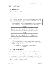
The following test and the corresponding test in Section 8.2.4.4 verify that all the DIP
switches are functioning correctly.
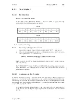
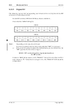
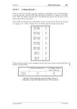
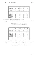
Set the DIP switches (SW301 & SW302) as shown in Table 8.3.
Check that the "ARM" LED lights.
SW301
SW302
Note:
Depending on the type of switch used:
if a switch is pushed down in the position labelled "OFF", it is at logic 1;
or
if the switch is pushed towards the LED indicators on the ASP card to the
"OFF" position, the bit value is a logic 1.
Table 8.3 DIP switch settings for testing the functionality of
the DIP switches.
Connect a 10k
Ω
pull up resistor to the "DIGOUT" line (pin 8A of connector PL-1)
and connect to +5V. Verify that it is at logic 1 (5V). The "DIGOUT" LED should be
extinguished.
0
1
1
1
0
1
0
1
D0
D1
D2
D3
D4
D5
D6
D7
0
1
0
1
0
1
0
1
D8
D9
D10
D11
D12
D13
D14
D15
Содержание T805
Страница 16: ...4 2 ASP Card Operation M805 00 30 04 95 Copyright TEL ...
Страница 44: ...7 18 Initial Programming Adjustment M805 00 30 09 96 Copyright TEL ...
Страница 70: ...14 1 2 PCB Information M805 00 30 04 95 Copyright TEL ...
Страница 81: ...M805 00 T805 04 PCB Information 14 3 19 Copyright TEL 30 09 96 T805 04 PCB Layout Bottom Side 220 01254 04 ...
Страница 82: ...14 3 20 T805 04 PCB Information M805 00 30 09 96 Copyright TEL T805 04 PCB Layout Top Side 220 01254 04 ...
Страница 89: ...Copyright TEL 30 09 96 M805 00 T805 Front Panel PCB Information 14 5 3 ...

