

5
missprints and technical changes reserved
Instruction & Operating Manual
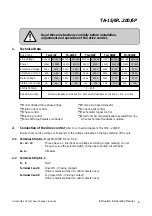
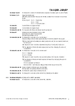
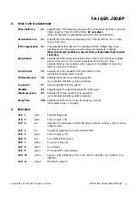
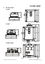
TA-15/6P...200/6P
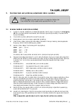
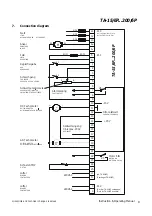
5.1 Armature feedback control (UA-controlled)
1)
Jumper
VI
must be installed if a controlled decelaration at drive stop is requested. For
Emergency
off
the connection between terminals 24 and 25 must be opened (Quick-stop). The drive will be
locked immidiately.
2)
Check all connections with an Ohm-meter for grounds.
3)
Install jumpers
I
and
VII
and also resistor R82 (22 KOhm).
4)
Check if line voltage corresponds with voltage indicated on the type marking. Select applicable
frequency, 50 Hz or 60 Hz with frequency-switch.
5)
Switch on line voltage. The following LED must light up:
LED 8
green
Line on
LED 5
green
+15V
LED 2
green
-15V
The diodes LED 4 (red) and the six diodes LED 1 (clear) will only light up briefly.
6)
Measure field voltage at terminal F+ and F- with a Multimeter (moving coil meter with at least 330
Ohm/Volt) 270V at 400V or 155V at 230V line-voltage. Measure voltage at potentiometer (terminal
5- and 6+) 10 V d.c. Set min. speed potentiometer during this measurement fully counter
clockwise.
7)
Potentiometer P4
Acceleration time, set in center position
Potentiometer P2
Deceleration time, set in center position
Potentiometer P3
IxR Compensation, set fully counter clockwise
Potentiometer P8
Stability, set in center position
Potentiometer P7
Jog speed, set fully counter clockwise
Potentiometer P10
Delay time, set fully clockwise
8)
Switch on the drive, LED 11 yellow (Drive on) and LED 9, green (drive release) will light up. When
the speed potentiometer is turned in clockwise direction, the armature voltage and the motor
speed respectively, will increase. This causes the six clear diodes LED 1 (Thyristor triggering) to
light up. Adjust potentiometer P9 (max. speed) for the requested armature voltage/motor speed.
Now set speed potentiometer fully counter clockwise, the output voltage must drop back to 0V.
Now adjust potentiometer P6 for the requested minimum speed.
9)
Switch off drive, Jog speed switch on.(LED 7 and LED 9 will light up). Adjust the requested jog
speed with potentiometer P7 (Jog speed).
10)
Adjust I x R compensation. Check for an apoprox equal speed with and without motor load in the
lower speed range. If the potentiometer is turned in clockwise direction the speed under load will
increase.
If the compensation potentiometer is set too high, the drive will become unstable.
Caution!
Do not use
any
Mega-Ohm-meter, buzzer or similar test instruments.
Test instruments must be galvanically seperated from a.c. line.
5.
Functional tests and preliminary adjustments before operation


