Coral FlexiCom 6000 Installation Manual
Hardware Installation Procedure
2-11
Eq
uipment Insta
llation
2
a
The manufacturer strongly recommends using a stranded three conductor
cable for the earth ground and DC power wiring, to minimize the inductance
of the current path. This cable should be jacketed or enclosed in a wire
conduit which meets local building, electrical, and/or fire codes.
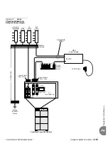
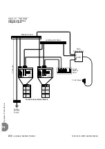
illustrates a typical power wiring diagram for a single-cabinet.
illustrates a typical power wiring diagram for two cabinets. Although two cabinets are
shown, the wiring is similar. Internal Power Supplies operate from 48VDC input. MPS
Main External Power Supply/Battery Chargers operate from 115/230VAC input and
supply 48VDC nominal output to the Coral system and optional stationary battery
plant. Stationary battery plants are highly recommended.
Wiring Procedure
1.
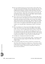
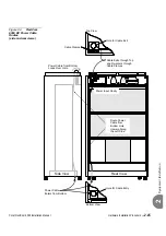
Power cables may be routed from above the Coral cabinet through a cable
entry point in the left rear corner of the cabinet top, or from below through a
similar entry point in the rear left corner of the cabinet bottom. Determine
whether cables should be routed from the top or bottom of the cabinet.
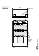
illustrates the possible power cable routing through the cabinet.
2.
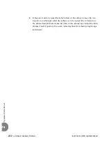
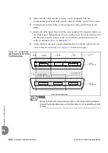
Release the two locking screws from the power input cavity and remove the
cover and retain it. Also remove the cable clamps and retain them, see
...................................................................................................
3
Ground and Power Wiring
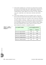
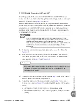
Electrical Hazard! Connect only a Protective Earth (PE) to the Coral system.
DO NOT
connect a separate Telecommunications Reference Conductor (TRC).
Resistance from the master ground to the building electrical ground should never
exceed 1.0 ohm. The master ground bar should be located in the switching room as
close as possible to the Coral. Any ground connection of equipment related to the
switching Coral system should ultimately connect to the master ground.
Содержание Coral FlexiCom 6000
Страница 2: ......
Страница 4: ......
Страница 18: ......
Страница 28: ...1 10 Introduction Coral FlexiCom 6000 Installation Manual Special Symbols Used in this Document 1 NOTES ...
Страница 32: ......
Страница 51: ...Coral FlexiCom 6000 Installation Manual Hardware Installation Procedure 2 19 Equipment Installation 2 NOTES ...
Страница 80: ...2 48 Hardware Installation Procedure Coral FlexiCom 6000 Installation Manual Equipment Installation 2 4 NOTES ...
Страница 86: ......
Страница 104: ...3 18 Initial Power Up Tests Coral FlexiCom 6000 Installation Manual Common Control Test 3 NOTES ...
Страница 110: ......
Страница 122: ...4 12 Software Installation Procedure Coral FlexiCom 6000 Installation Manual System Database Control 4 NOTES ...
Страница 134: ...4 24 Software Installation Procedure Coral FlexiCom 6000 Installation Manual Upgrading the Coral Version 4 NOTES ...
Страница 143: ...Coral FlexiCom 6000 Installation Manual Chapter 5 External Connections 5 1 External Connections 5 1 ...
Страница 144: ......
Страница 146: ...5 2 External Connections Coral FlexiCom 6000 Installation Manual External Connections 5 NOTES ...
Страница 147: ...Coral FlexiCom 6000 Installation 0DQXDO Chapter 6 Cabinet Descriptions 6 1 Cabinet Descriptions 6 1 ...
Страница 148: ......
Страница 190: ...6 42 Cabinet Descriptions Coral FlexiCom 6000 Installation Manual Cabinet Descriptions 6 NOTES ...
Страница 191: ...Coral FlexiCom 6000 Installation Manual Chapter 7 Power Supplies 7 1 PPS 7 1 7 2 RPS 7 9 7 3 PS ATS 7 19 ...
Страница 192: ......
Страница 210: ...7 18 Power Supplies Coral FlexiCom 6000 Installation Manual RPS Ring Generator Power Supply Unit 7 ...
Страница 224: ......
Страница 322: ...8 98 Common Control Cards Coral FlexiCom 6000 Installation Manual CLA ATS CoraLINK Adapter Card 8 NOTES ...
Страница 338: ...8 114 Common Control Cards Coral FlexiCom 6000 Installation Manual PBD24S Backplane Card 8 NOTES ...
Страница 339: ......


