4-4
Software Installation Procedure
Coral FlexiCom 6000 Installation Manual
System Database Contr
o
l
4
Use the
0-Save Database
Option to copy the current system database (from the 32GC
RAM), at any time, to the CFD card for backup or restore purposes. For Hot Standby
systems, this option may only be requested from the Active side. The database is
copied to both flash memories simultaneously. After a successful Save, each PI
Terminal reports which database was saved successfully. If the database was not saved
successfully, a PI Alarm message is displayed on the PI terminal(s).
The SAVE procedure is only possible from the Active side of a Hot Standby
system. However, messages indicating a successful copy appear on both
system sides.
1.
Verify that the system time and date are correct (press Control-T to check).
Update through the Time and Date branch
(Route: TIME)
of the system
database, if necessary.
2.
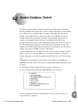
From the Database Control Branch: Disk Menu
(Route: 0, 10, 2, 0)
, press
0
to
save the database to the CFD(s). The system prompts for the selection of a
destination file number, either DB0.DEF or DB1.DEF, with:
DEST FILE #(0,1) -
The DB0.DEF file is used for automatic saves at a preset time each day (see
Automatic Daily Database Back-Up on page 4-10
), and is usually a more updated
file than the DB1.DEF file. The DB1.DEF file is referred to as the
technician
copy
of the database, and should be saved each time installation or
maintenance personnel make changes to the database.
3.
Press
0
or
1
, according to
below, to choose to which file to save,
DB0.DEF or DB1.DEF. The default entry is 0 (DB0.DEF).
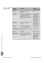
Table 4-1
CFD File
Descriptions
At the system prompt the following parameter is displayed:
EXECUTE (Y/N) -
...................................................................................................
1
Saving the System Database
Database File
Name
PI
Entry
File Description
DB0.DEF
0
Daily back-up automatically at a preset time.
DB1.DEF
1
Technician copy for manual back-up.
Содержание Coral FlexiCom 6000
Страница 2: ......
Страница 4: ......
Страница 18: ......
Страница 28: ...1 10 Introduction Coral FlexiCom 6000 Installation Manual Special Symbols Used in this Document 1 NOTES ...
Страница 32: ......
Страница 51: ...Coral FlexiCom 6000 Installation Manual Hardware Installation Procedure 2 19 Equipment Installation 2 NOTES ...
Страница 80: ...2 48 Hardware Installation Procedure Coral FlexiCom 6000 Installation Manual Equipment Installation 2 4 NOTES ...
Страница 86: ......
Страница 104: ...3 18 Initial Power Up Tests Coral FlexiCom 6000 Installation Manual Common Control Test 3 NOTES ...
Страница 110: ......
Страница 122: ...4 12 Software Installation Procedure Coral FlexiCom 6000 Installation Manual System Database Control 4 NOTES ...
Страница 134: ...4 24 Software Installation Procedure Coral FlexiCom 6000 Installation Manual Upgrading the Coral Version 4 NOTES ...
Страница 143: ...Coral FlexiCom 6000 Installation Manual Chapter 5 External Connections 5 1 External Connections 5 1 ...
Страница 144: ......
Страница 146: ...5 2 External Connections Coral FlexiCom 6000 Installation Manual External Connections 5 NOTES ...
Страница 147: ...Coral FlexiCom 6000 Installation 0DQXDO Chapter 6 Cabinet Descriptions 6 1 Cabinet Descriptions 6 1 ...
Страница 148: ......
Страница 190: ...6 42 Cabinet Descriptions Coral FlexiCom 6000 Installation Manual Cabinet Descriptions 6 NOTES ...
Страница 191: ...Coral FlexiCom 6000 Installation Manual Chapter 7 Power Supplies 7 1 PPS 7 1 7 2 RPS 7 9 7 3 PS ATS 7 19 ...
Страница 192: ......
Страница 210: ...7 18 Power Supplies Coral FlexiCom 6000 Installation Manual RPS Ring Generator Power Supply Unit 7 ...
Страница 224: ......
Страница 322: ...8 98 Common Control Cards Coral FlexiCom 6000 Installation Manual CLA ATS CoraLINK Adapter Card 8 NOTES ...
Страница 338: ...8 114 Common Control Cards Coral FlexiCom 6000 Installation Manual PBD24S Backplane Card 8 NOTES ...
Страница 339: ......


