2. Minimize pipe strain on pump by using pipe hangers
on the suction and discharge lines.
3. Position vertical and horizontal piping so bolt-holes on
pump and companion flanges match. Do not force the
suction and discharge lines into position. This may cre-
ate excess stress on the pump casing and flanges.
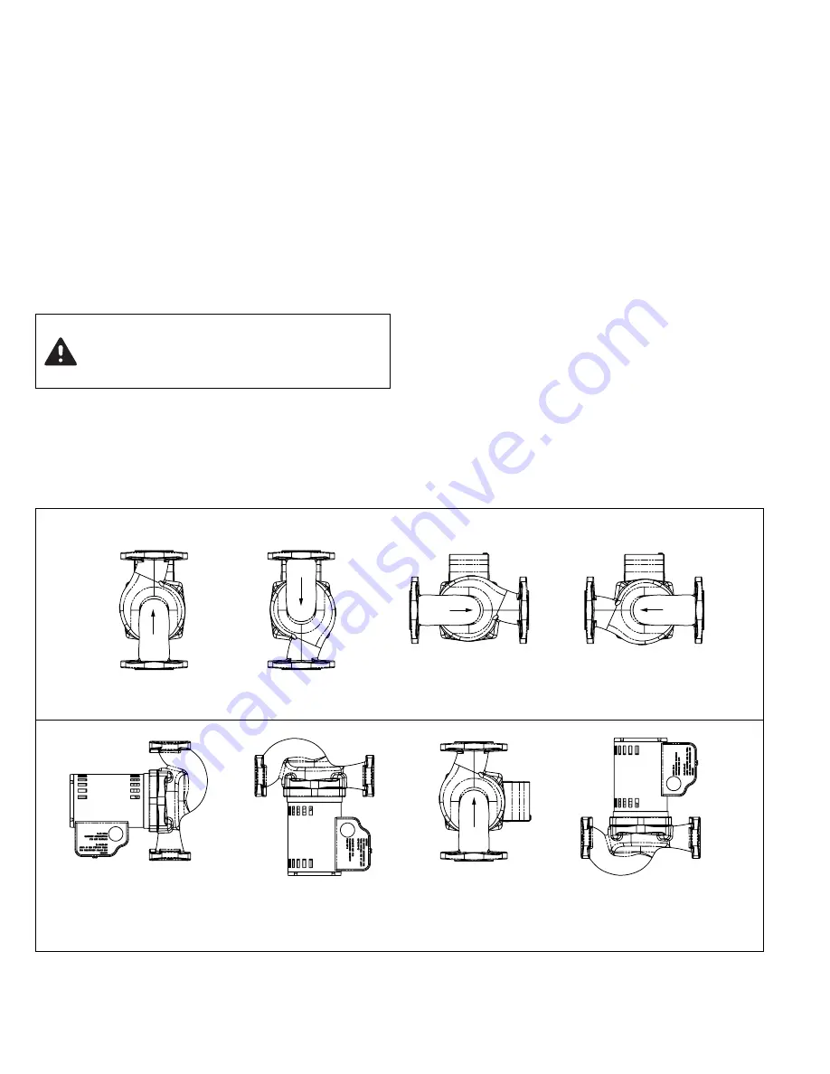
B. Mounting Position:
• Always install pump with the motor shaft in the hori-
zontal position and the capacitor/conduit box oriented
on top of the motor housing, as shown in Fig. 1.
• Standard pump body mounting position is with the flow
in the up-discharge direction (body position #3). The
pump body may be field-rotated in any direction to
accommodate system piping and flow direction.
• Be sure to align the arrow on the casing with desired
flow direction.
C. Electrical Wiring:
• All electrical wiring must be installed by a licensed
electrician in accordance with local and national codes
and regulations.
• Electrical supply and grounding wires must be suitable
for at least 90ºC (194ºF).
• 1400 Series circulators are thermally protected and do
not require external overload protection.
1. Be sure all electrical power to pump is disconnected
and locked-out before proceeding with wiring.
2. Loosen capacitor/conduit box screw and remove cover.
3. Attach appropriate size connector to one of the two
knock-out holes in the capacitor/conduit box.
4. Using minimum 18 AWG wire, connect the hot and
neutral leads from the electrical supply to the respec-
tive black and white leads in the capacitor box.
5. Connect the ground wire to the green ground screw in
the capacitor box.
6. Replace capacitor/conduit box cover.
7. Insert plastic plug provided in unused knock-out hole.
RECOMMENDED
NOT RECOMMENDED
FLOW
FLOW
FLOW
FLOW
FLOW
CAUTION: Do not support, suspend or brace
pump motor or early failure may result.
Support provided by casing is sufficient for
structural integrity of pump
Fig. 1 – Installation Positions


