


iWorx® MPU2
505-009, Effective: June 30, 2015
21
© 2015 Taco Electronic Solutions, Inc.
Heating Stages
The heating sequence is initiated when the current operating mode calls for heat. The electric heating stages are
sequenced based on the supply air temperature, heating setpoint and control band. When the supply air temperature
drops below the heating setpoint minus the control band, a stage is turned on. If the supply air temperature remains
below the control band for an additional time-period, the next available stage is turned on. If all zone temperature read-
ings are within 0.5
°F of their setpoints, the next stage does not cycle on. This cycle continues until all available stages
have been energized.
As the supply air temperature rises above the heating setpoint, the first available stage is turned off. If the supply air
temperature remains above the heating setpoint for an additional time-period, the next available stage is turned off.
This cycle continues until all available stages have been de-energized. If the supply air temperature rises above the
heating setpoint plus control band all of the stages immediately cycle off.
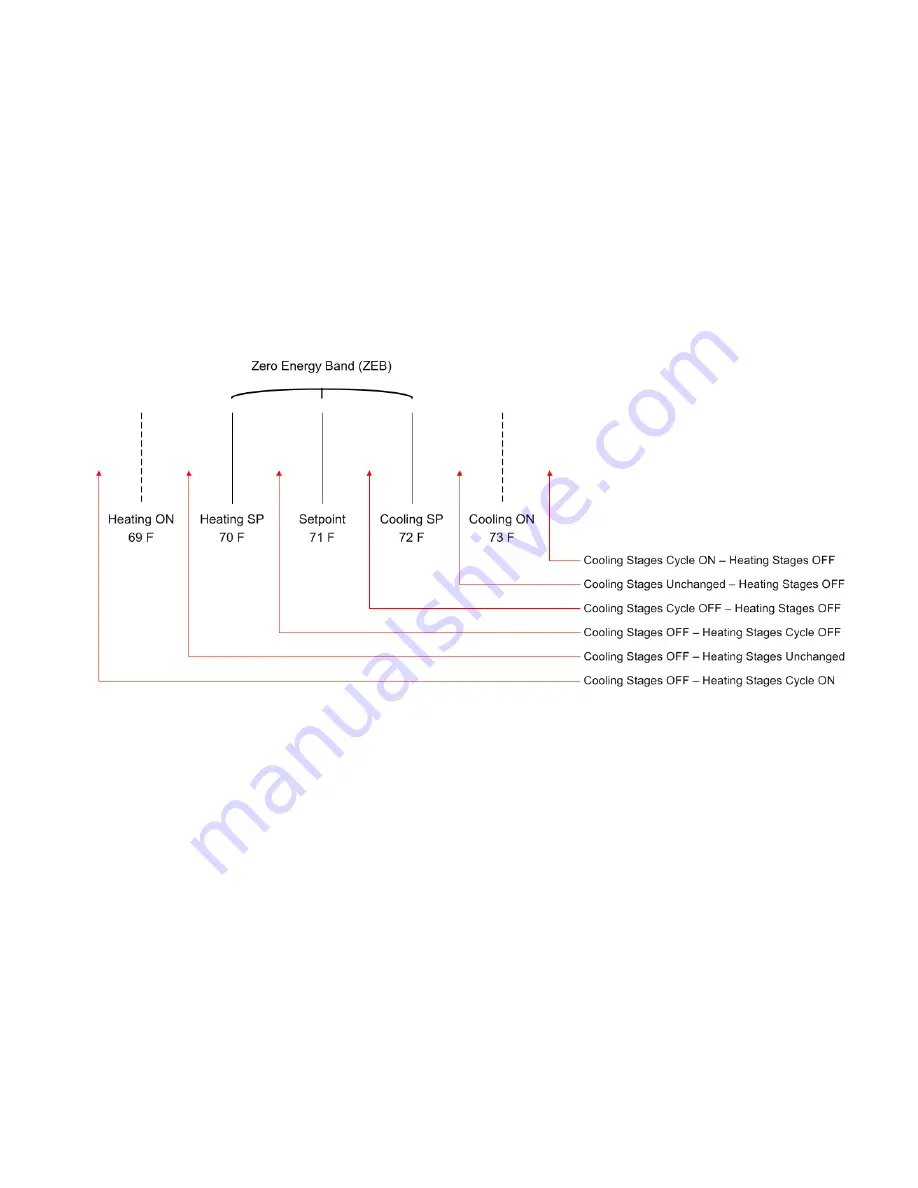
Figure 8: Staged Heating and Cooling
Heating with Floating Point Control
The heating stage outputs can be configured for floating point control of a heating valve. Floating point control is
enabled when heating stages are set to zero and the
Heating Valve Travel Time
is non-zero. The heating stage 1 out-
put is the valve open signal and the heating stage 2 output is the valve close signal.
After a reset, the floating point valve is calibrated by closing the valve for a period of the travel time. This ensures that
the valve is fully closed. When the valve is at its calculated 0% or 100% position, the valve is overdriven for 30 seconds
to ensure that the valve is fully closed or open.
The floating point control is similar to the heating modulated algorithm. If the supply temperature is below the heating
setpoint, the valve is driven open. When the supply temperature is above the heating setpoint, the vale is driven close.
There is a +-1.0 °F (0.55 °C) deadband around the setpoint to prevent the valve from dithering. During mixed air low
limit alarms, the heating valve is driven to 100%.
Heating with Modulated Output (Valve or Variable Speed Circulator)
The calculated heating loop setpoint is derived from the heating setpoint and the loop proportional gain.
CalcHeatingLoopSp = CalcHeatingSp- ½(Kp)


