


____________________________________________________________________________________________________
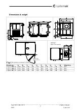
Topvex SR07, SR09, SR11
E
Installation instruction
205870
Systemair AB
16
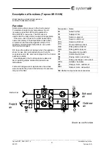
Components
Heat exchanger
Topvex has a high efficient rotating heat exchanger. Required supply air temperature is therefore normally
maintained without adding additional heat via the built in re-heater battery (water or electric). The operation
of the heat exchanger is automatic and depends on the set temperature.
The heat exchanger is not removable and has to be cleaned inside the unit.
Heater battery
Topvex has a built in heater battery (water or electric). The operation of the heating battery is automatic
and dependent on the set temperature.
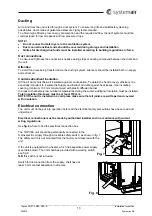
Electrical heater
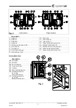
The heating rods are located in the heater beside the supply air fan
(see fig. 2 and 3)
and the material is
stainless steel. The electric heating coil has both automatic and manual overheating protection. The power
demand of the electric heating coil is controlled by a triac power regulator (Pulser) according to the desired
supply/extract or room air temperature that is set in the control panel.
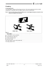
Hot water heater
The hot water coil is located beside the supply air fan
(see fig. 2)
. The coil is mounted with the connection
pipes projecting from the side of the unit and is therefore easy to connect
(see fig. 1)
. The material is
copper piping with a frame of galvanized sheet steel and aluminum fins. The coil has a venting nipple and
an immersion sensor as frost guard. If there is a risk of freezing in the hot water coil, the control valve is
forced open to prevent freezing. If there is still a risk of freezing, the unit is stopped and the outdoor sir
dampers (accessory) are closed.
Control panel
The SCP control panel is delivered with a 10m cable that is pre-connected to the panel and with a fast
coupling contact, pre-connected to the Topvex unit. The contact is connected to the
Corrigo
controller in
the electrical connection box (
fig. 3)
. The cable can be unscrewed in the back of the control panel (
fig 5
).
General information is shown in (
fig 5
).
How to operate
The menus in the Corrigo E-controller are organized in a horizontal tree structure. The UP/DOWN-buttons
are used to move between menus at the present menu level. The RIGHT/LEFT buttons are used to move
between menu levels. When changing parameters the UP/DOWN buttons are used to increase/ ecrease
the value of the parameter and the RIGHT/LEFT buttons to move between digits within the parameter.
The OK button is used to confirm the choice of a parameter setting.
The C button is used to abort an initiated parameter change and restore the original value.
The ALARM button is used to access the alarm list.
Changing parameters
In some menus there are parameters that can be set. This will be indicated by the LED
flashing. To
change a parameter, first press the OK button, the LED
changes to a steady light. A cursor will appear
at the first settable value. If you wish to change the value, do so by pressing the UP/DOWN buttons. In
numbers containing several digits you can move between the digits using the LEFT/RIGHT-buttons.
When the desired value is displayed presses OK. If there are further settable values displayed the cursor
will automatically move to the next one. To pass a value without changing it, press RIGHT.
To abort a change and return to the initial setting, press and hold the C-button until the cursor disappears.
Содержание Topvex SR07 E
Страница 27: ......


