background image

28/55 | 

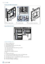
S-BA2

125

≥50

50

12,5

141

50

141

125

50

141

H

1

 ×

 W

1

H

1

 ×

 W

1

H

1

 ×

 W

1

>125

H

 ×

 W

H

 ×

 W

H

 ×

 W

F1

Y

9

(mm)

F3

1

5

F1

Y

11

(mm)

F3

1

5

F1

Y

10

(mm)

F3

1

5

H

1

 =

 H

+1

00

W

1

 = W

+28

5

W

1

 = W

+28

0

H

W

3

4

1

F1

Y

Y

Содержание A-S-BA2

Страница 1: ...S BA2 Smoke Control Damper AA multi Handbook...

Страница 2: ...2 55 S BA2 Table of Contents Overview 3 Technical Parameters 6 Diagrams 8 Dimensions 14 Ordering Code 17 Product Handling 18 Installation 23 Electrical Parameters 46 Operation Manual 52...

Страница 3: ...h EN 1751 Fire Resistivity S BA2 smoke control dampers have a CE certification that meets the EU s Construction Products Regulation and complies with Standard EN 12101 8 2011 EN 1366 10 2011 A1 2017 a...

Страница 4: ...0 24 other communication units on demand Design The casing and the blades of the S BA2 are made of a galvanized sheet metal A foam seal with an intumescent seal that prevents leaks of heat or smoke Th...

Страница 5: ...mper blade P3 Actuator P4 Supply and communication unit only for BST0 activation type P5 Holder for communication unit only for B24T W activation type P6 Sheet metal grille P7 Threaded inserts for duc...

Страница 6: ...721 3 3 Product protected from Weather rain and water from other sources Condensation Cannot form on the product Icing Cannot form on the product Access for Inspection The inspection is possible throu...

Страница 7: ...sitivity Pass Response delay response time Opening closure time proven Duration 60 s 90 Operational reliability Cmod 20 000 cycles modulated Fire resistance EI 90 vew i o S1000Cmod AAmulti EI 120 ved...

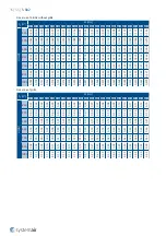
Страница 8: ...p A weighted sound power level in dB A 1000 2000 5000 m h 500 1000 2000 l s 5 10 50 Pa W 200 H 500 W 400 H 500 W 600 H 500 W 800 H 500 25 30 35 40 45 50 55 25 30 35 40 45 50 55 60 25 30 35 40 45 50 55...

Страница 9: ...50 55 25 30 35 40 45 50 55 60 25 30 35 40 45 50 55 60 25 30 35 40 45 50 55 S BA2 00 Pressure drop A weighted sound power level in dB A 2000 5000 10000 m h 500 1000 2000 l s 5 10 20 Pa W 200 H 750 W 4...

Страница 10: ...35 40 45 50 55 25 30 35 40 45 50 55 60 65 25 30 35 40 45 50 55 60 65 25 30 35 40 45 50 55 S BA2 01 Pressure drop A weighted sound power level in dB A 2000 5000 10000 m h 500 1000 2000 l s 5 10 20 Pa...

Страница 11: ...0 45 50 55 25 30 35 40 45 50 55 60 25 30 35 40 45 50 55 60 65 25 30 35 40 45 50 55 S BA2 01 Pressure drop A weighted sound power level in dB A 2000 5000 10000 m h 500 1000 2000 l s 5 10 50 Pa W 200 H...

Страница 12: ...0 45 50 55 25 30 35 40 45 50 55 60 25 30 35 40 45 50 55 60 65 25 30 35 40 45 50 55 S BA2 11 Pressure drop A weighted sound power level in dB A 1000 5000 10000 m h 500 1000 2000 l s 5 10 20 Pa W 200 H...

Страница 13: ...0 45 50 55 25 30 35 40 45 50 55 60 25 30 35 40 45 50 55 60 65 25 30 35 40 45 50 55 S BA2 11 Pressure drop A weighted sound power level in dB A 1000 5000 10000 m h 500 1000 2000 l s 5 10 50 Pa W 200 H...

Страница 14: ...14 55 S BA2 Dimensions Weights Dimensions W W 20 H H 20 W 222 H 40 H 50 W 230 145 125 10 141 10 10 2 mm S BA2 NOTE Inclusive grille...

Страница 15: ...354 0 360 0 387 0 407 0 421 0 454 0 461 0 488 0 521 1000 0 099 0 118 0 137 0 156 0 176 0 199 0 214 0 226 0 253 0 256 0 291 0 330 0 368 0 407 0 414 0 445 0 468 0 484 0 522 0 530 0 561 0 599 Free area...

Страница 16: ...3 22 4 23 3 24 3 25 3 26 3 27 4 27 2 28 2 28 5 29 6 29 7 30 6 31 6 1000 20 5 21 0 21 6 22 1 22 7 23 3 23 8 24 0 25 0 25 1 26 1 27 2 28 6 29 7 29 8 30 8 31 6 31 9 33 0 33 1 34 2 35 3 Weights of grille...

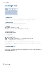
Страница 17: ...AL 9003 B Type of Activation B230 230V AC Belimo actuator B24 24V AC DC Belimo actuator B24 W 24V AC DC Belimo actuator wire connector for supply and communication unit B24 SR 24V AC DC Belimo actuato...

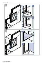
Страница 18: ...ix the mechanism cover by previously removed screws 4 Placing the damper Prepare the opening and or duct connection surfaces as per the desired installation type Carefully lift the smoke control dampe...

Страница 19: ...19 55 S BA2 5 1 1 2 B A1 A2 3 A1 B A2...

Страница 20: ...20 55 S BA2 C 4 1 8 1 Fx C1 C2...

Страница 21: ...21 55 S BA2 F3 5 2 D E F3 D1 D2 5 E1 E2 6...

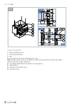
Страница 22: ...ng 1 Smoke control damper S BA2 2 Connected metal ductwork 5 Grille 8 Support brick metal stud or wood stud not part of damper F3 Self tapping screw size 4 2 4 8 length 80 mm e g DIN 7981C DIN 7982C F...

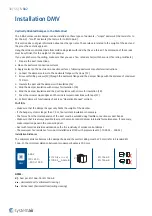
Страница 23: ...on using plaster mortar concrete Filling 3 Soft Soft Installation using mineral wool filing DMH In the metal duct installation horizontally oriented damper DMV In the metal duct installation verticall...

Страница 24: ...this structure There is a gap between the smoke control damper and the wall or ceiling opening It is permitted to increase the gap size up to 1 5 times but up to maximum of additional 30 mm It is per...

Страница 25: ...CAUTION Make sure that the primary parts of the damper do not become dirty If they become dirty they will not operate correctly a To prevent damage cover the primary parts during filing installation b...

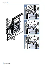
Страница 26: ...0 50 141 H 1 W 1 12 5 125 50 50 12 5 141 125 50 141 125 50 141 H 1 W 1 H 1 W 1 H 1 W 1 H W H W H W H W Y3 mm F3 1 F1 F2 Y1 mm F3 1 F1 F2 Y4 mm F3 1 F2 Y2 mm F3 1 F1 F2 F1 2 2 2 2 H 1 H 100 W1 W 280 W...

Страница 27: ...12 5 125 50 50 12 5 141 125 50 141 125 50 141 H 1 W 1 H 1 W 1 H 1 W 1 H 1 W 1 H W H W H W H W Y7 mm F3 1 F1 F2 F1 F2 Y5 mm 5 F3 1 5 2 Y8 mm F3 1 F1 F2 F1 F2 Y6 mm 5 F3 1 5 2 2 2 W1 W 285 H 1 H 100 W1...

Страница 28: ...28 55 S BA2 125 50 50 12 5 141 50 141 125 50 141 H 1 W 1 H 1 W 1 H 1 W 1 125 H W H W H W F1 Y9 mm F3 1 5 F1 Y11 mm F3 1 5 F1 Y10 mm F3 1 5 H 1 H 100 W1 W 285 W1 W 280 H W 3 4 1 F1 Y Y...

Страница 29: ...ected metal ductwork 3 Concrete masonry cellular concrete wall or ceiling 4 Flexible plasterboard wall 4a 2 layers of plasterboard fireproof plate type F EN 520 4b Vertical CW profiles 4c Horizontal C...

Страница 30: ...sistive coating F5 on the wool segments 5 Fill the area between the wall and the damper with mineral wool segments F4 CAUTION Make sure that the filling will not cause deformation to the damper 6 Use...

Страница 31: ...125 50 50 141 H 1 W 1 12 5 10 125 50 50 12 5 10 141 125 50 141 10 125 50 10 141 H 1 W 1 H 1 W 1 H 1 W 1 H W H W H W H W W H 3 4 2 1 F4 F5 Y Y3 mm F3 1 F4 F5 F2 Y1 mm F3 1 F4 F5 F2 Y4 mm F3 1 F5 F2 Y2...

Страница 32: ...50 12 5 10 141 125 50 141 10 125 50 10 141 H 1 W 1 H 1 W 1 H 1 W 1 H 1 W 1 W1 W 285 H 1 H 100 W1 W 280 H W H W H W H W H W Y7 mm F3 1 F4 F5 F2 F4 F2 Y5 mm 5 F3 1 F5 5 2 Y8 mm F3 1 F4 F5 F2 F4 F2 Y6 m...

Страница 33: ...55 S BA2 125 50 50 12 5 10 141 50 141 125 50 10 141 H 1 W 1 H 1 W 1 H 1 W 1 125 10 H 1 H 100 W1 W 280 W1 W 280 H W H W H W H W F4 Y9 mm F3 1 F5 5 F4 Y11 mm F3 1 F5 5 F4 Y10 mm F3 1 F5 5 3 4 1 F4 F5 Y...

Страница 34: ...W1 W 285 W1 W 280 125 50 12 5 141 10 50 H 1 W 1 125 141 10 50 H 1 W 1 125 141 10 50 H 1 W 1 W 180 H H W 180 H W 180 H W 180 6 1 F4 F5 3 4 5 Y F3 1 F5 5 F4 F2 Y12 mm F3 1 F5 5 F4 F2 Y13 mm 6 6 F3 1 F5...

Страница 35: ...Concrete masonry cellular concrete wall or ceiling 4 Flexible plasterboard wall 4a 2 layers of plasterboard fireproof plate type F EN 520 4b Vertical CW profiles 4c Horizontal CW profiles 4d Mineral w...

Страница 36: ...ulation F6 5 Bind the damper insulation with screws for insulation F8 6 Bind the damper insulation and the duct insulation with screws for insulation F8 7 Cover the mineral wool edges and the mineral...

Страница 37: ...ductwork 5 Grille F2 Screw M6 20 25 mm maximum fixing torque is 4 5 Nm NOTE Following insulation system can be replaced for another smoke control duct system with equal or higher thickness and or equ...

Страница 38: ...per insulation with screws for insulation F8 6 Bind the damper insulation and the duct insulation with screws for insulation F8 7 Cover the mineral wool edges and the mineral wool connections with tap...

Страница 39: ...ductwork 5 Grille F2 Screw M6 20 25 mm maximum fixing torque is 4 5 Nm NOTE Following insulation system can be replaced for another smoke control duct system with equal or higher thickness and or equ...

Страница 40: ...lation F6 5 Bind the damper insulation with screws for insulation F8 6 Bind the damper insulation and the duct insulation with screws for insulation F8 7 Cover the mineral wool edges and the mineral w...

Страница 41: ...S BA2 2 1 5 F6 Y 2 X 1 F6 Y 5 W 180 H 125 W H 80 1 5 F6 180 80 2 F7 F8 F9 50 141 210 1 5 F6 F7 F8 141 2 F2 80 180 80 H W 125 50 125 i i D2H mm mm mm Y2 D1H Y D2H X D2H mm Y1 D1H D1H F9 125 125 125 Y Y...

Страница 42: ...aximum fixing torque is 4 5 Nm NOTE Following insulation system can be replaced for another smoke control duct system with equal or higher thickness and or equal or higher bulk density F6 Duct insulat...

Страница 43: ...on F6 5 Bind the damper insulation with screws for insulation F8 6 Bind the damper insulation and the duct insulation with screws for insulation F8 7 Cover the mineral wool edges and the mineral wool...

Страница 44: ...4 55 S BA2 mm mm mm mm Y D1V X D1V Y D1V X D1V 5 F9 F2 1 F7 2 F6 125 141 W H 50 125 80 80 F8 125 125 125 125 F7 F6 80 W H 1 5 141 F2 F9 50 125 125 Y 2 X F6 1 5 5 Y X F6 2 1 F8 80 80 80 D1V D1V Y Y X X...

Страница 45: ...imum fixing torque is 4 5 Nm NOTE Following insulation system can be replaced for another smoke control duct system with equal or higher thickness and or equal or higher bulk density F6 Duct insulatio...

Страница 46: ...50 355 400 450 500 550 560 600 630 650 700 710 750 800 H mm 250 375 500 625 750 875 1000 B230 AC 230 V 50 60 Hz 7 VA BEN230 B24 AC 50 60 Hz DC 24 V 6 VA BEN24 B24 W AC 50 60 Hz DC 24 V 6 VA BEN24 ST B...

Страница 47: ...When the power supply is connected to wires 1 and 2 the actuator moves to the CLOSED position NOTES CAUTION Main power supply voltage Parallel connection of more actuators possible when the power cons...

Страница 48: ...When the power supply is connected to wires 1 and 2 the actuator moves to the CLOSED position NOTES CAUTION Main power supply voltage Parallel connection of more actuators possible when the power con...

Страница 49: ...ply is connected to wires 1 and 2 the actuator moves to the CLOSED position NOTES CAUTION Main power supply voltage Parallel connection of more actuators possible when the power consumption and switch...

Страница 50: ...TION Main power supply voltage Parallel connection of more actuators possible when the power consumption and switching threshold is observed Operating range Y DC 0 2 10 V Input Impedance 100 k Positio...

Страница 51: ...tuator to the desired position Two LEDs in the device indicate the function status LED Status Function Yellow Flashing Damper moves OPEN Yellow On Damper OPEN Green Flashing Damper moves CLOSED Green...

Страница 52: ...that you receive the open signal or wires S1 and S2 are connected NOTE The actuator can be moved to open position with manual crank supplied with the actuator 3 Closing the damper Depending on the ac...

Страница 53: ...ems of the damper The internal casing of the damper The sealings The foaming material The condition of the damper blade How accurately the damper blade closes when it is against the backstop in the cl...

Страница 54: ...S BA2 Supplement If you find differences from the terms and the technical specifications that are in this manual speak to the manufacturer We reserve the right to make changes to the product without n...

Страница 55: ...Systemair DESIGN 2021 09 16 Handbook_S_BA2_en GB...

Отзывы: