


SS-300-018
5
I56-3371-003R
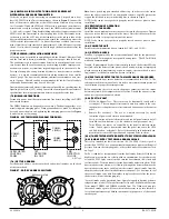
1) Install DCOIL in housing pocket insuring that arrow is pointing toward detector
2) Install DCOIL mounting screw
3) Connect each DCOIL lead to a Test Coil Terminal
See
Figure 9
below for reference.
fIgURE 9. DNRW WITh OPTIONAL TEST COIL
TEST COIL TERMINALS
TEST COIL
TEST COIL SCREW
H0561-00
fIgURE 10. WIRINg DIAgRAM fROM DNRW TO RTS451/RTS151/
RTS451kEy/RTS151kEy:
EXTERNAL
(-) POWER (+)
SUPPLY
*
RTS451/151,
RTS451/151KEY
REMOTE TEST STATION
LED OPTION
1 PER UNIT
10mA CURRENT DRAW
TEST COIL OPTION
1 PER UNIT
95mA CURRENT DRAW
4
5
3
2
1
TEST COIL +
TEST COIL –
COMM +
OUT (CONV ONLY) +
COMM –
RA/RTS –
RA +
RTS +
NOTE: THE RTS451/151, RTS451/151KEY TEST COIL
CIRCUIT REQUIRES AN EXTERNAL 24 VDC POWER
SUPPLY WHICH MUST BE UL LISTED.
NOTE: THE USE OF A REMOTE TEST STATION REQUIRES THE
INSTALLATION OF AN ACCESSORY COIL, PART NUMBER DCOIL, SOLD
SEPARATELY.
11.2 RTS451/RTS151/RTS451kEy/RTS151kEy REMOTE TEST
STATION WITh OPTIONAL SENSOR REMOTE TEST CAPABILITy
To install the RTS451/RTS151/RTS451KEY/RTS151KEY, using the sensor with
remote test capability connect the device as shown in Figure 11; wire runs
must be limited to 25 ohms or less per interconnecting wire.
H0571-07
CAUTION
Canned aerosol simulated smoke (canned smoke agent) formulas will vary by
manufacturer. Misuse or overuse to these products may have long term adverse
effects on the smoke detector. Consult the canned smoke agent manufacturer’s
published instructions for any further warnings or caution statements.
[9]DETECTOR CLEANINg PROCEDURES
Notify the proper authorities that the smoke detector system is undergoing
maintenance, and that the system will temporarily be out of service. Disable
the zone or system undergoing maintenance to prevent unwanted alarms and
possible dispatch of the fire department.
[9.1]DETECTOR SENSOR
1. Remove the sensor to be cleaned from the system.
2. Remove the sensor cover by pressing firmly on each of the four removal
tabs that hold the cover in place.
3. Vacuum the screen carefully without removing it. If further cleaning is
required continue with Step 4, otherwise skip to Step 7.
4. Remove the chamber cover/screen assembly by pulling it straight out.
5. Use a vacuum cleaner or compressed air to remove dust and debris from
the sensing chamber.
6. Reinstall the chamber cover/screen assembly by sliding the edge over the
sensing chamber. Turn until it is firmly in place.
7. Replace the cover using the LEDs to align the cover and then gently
pushing it until it locks into place.
8. Reinstall the detector.
[9.2]REINSTALLATION
1. Reinstall the detector in its housing.
2. Restore system power.
3. Perform Detector Check.
4. Notify the proper authorities testing has been completed and the smoke
detector system is back in operation.
[10]SENSOR REPLACEMENT
1. Remove the sensor head by rotating counterclockwise.
2. Pull gently to remove it.
3. To replace the sensor head, align the mounting features and rotate clock-
wise into place.
[11] OPTIONAL ACCESSORIES
Optional accessories include RA400Z/RA100Z, RTS451/RTS151 and RTS-
451KEY/RTS151KEY
fIgURE 8. WIRINg DIAgRAM fOR DNRW TO RA400Z/RA100Z:
(+)
(-)
RA400Z/RA100Z
– RA
+ RA
REMOTE ALARM LED
OPTION 1 PER UNIT
H0570-03
Note: If using a RA400Z, the tab should be broken for use with the intelligent
duct smoke detector. If using RA100Z, ensure that jumper is removed.
[11.1]RTS451/RTS151/RTS451kEy/RTS151kEy REMOTE TEST
STATION WITh OPTIONAL TEST COIL
The RTS451/RTS151/RTS451KEY/RTS151KEY Remote Test Station facilitates
test of the alarm capability of the duct smoke detector. These accessories
provide the stimulus to initiate an alarm condition at the detector. The DNRW
duct smoke detector must be reset by the system control panel.
NOTE:
The use of a remote test station requires the installation of an acces-
sory coil, part number DCOIL, sold separately.
RTS451/RTS451KEY
RTS151/RTS151KEY
JUMPER
4
5
3
2
1
TEST COIL +
TEST COIL –
COMM +
OUT (CONV ONLY) +
COMM –
RA/RTS –
RA +
RTS +
11.3 ADDITIONAL MODULE OPTION
The DNRW can also accommodate a relay or control module (sold separately)
within the power board side of the housing. The relay or control module must
be listed as compatible to the fire alarm control panel.
Physical Module Mounting
1) Remove the breakaway tabs at the four corners of the module
2) Locate the module at right most corner of the power board. The upper
left corner mounting hole of the module will align with a screw boss in
the housing.
3) Install a # 8 x 3/8” Plastite screw at the screw boss location
Note: See the corresponding module Installation Instructions for general de-
scription, control panel compatibility, wiring and ratings.
HO633-00
fIgURE 11. RTS451/RTS451kEy/RTS151/RTS151kEy:


