SYS TEC electronic GmbH
L-1589e-04
Hardware Manual ECUcore-1021
Page 25/30
Classification: Release
3.6
PCI Express
The module supports two PCIe2.0 interfaces. For each interface a 100MHz reference clock output is
available. No additional clock buffer on carrier board is needed. The design-in information in /3/ should be
noted.
3.7
SGMII
Th
e module supports up to two SGMII interfaces to connect GBE Phy’s. The SGMII interface needs no
reference clock. The 25MHz clock for the Phy can be derived from module clock outputs
(CLK1_25M_3V3). The design-in information of the Phy vendor should be noted.
3.8
SGMII/SATA
SGMII and SATA3.0 share the same SERDES-Lanes of LS1021A. SATA3.0 requires AC coupling
capacitors of 12nF directly at the SATA connector for RX and TX signal lines. In /3/ this would have
provided on the modules.
SGMII requires for the RX and TX signal lines an AC coupling capacitor of 100nF at the input side of the
Phy. The SGMII and the SATA requirements are contrary to /3/. For this reason, the specific AC coupling
capacitors must be located on the Carrier Board.
3.9
ETHERNET Interface considerations
The module provides one Ethernet port (GbE0) with integrated Phy (Additionally, up to two more
interfaces can be supported with SGMII-
Phy’s on the Carrier Board). The interface supports 4 wire
10/100BASE-Tx and 8 wire 1000BASE-T as well. The interface signals can be used to connect to LAN
connector with internal or external isolation magnetics on the Carrier Board. Additionally to the
recommendations in /3/ for the connections of the magnetics to the Phy the following should be notes:
- Termination resistors required by the module Phy are present on the Module.
- The magnetic center tab must be terminated with a 100nF/±10% capacitance to ground. There is no
center tab reference signal on the Module connector.
- The module Phy provides two LED output pins (see Table 6). Each LED output pin can directly drive an
LED with a series resistor of typically 220Ω to 470Ω at 3.3V.
SYS TEC has acquired a pool of MAC addresses. The MAC address for the first Ethernet interface GbE0
is barcode-labelled and attached on the Module.
3.10 I2C Interface considerations
The I2C bus is a two-wire serial bus. The LS1021A supports up to three interfaces of I2C. The I2C1
interface is always available the other interfaces can also be occupied with an alternative function
depending on RCW.
Both signal lines (I2Cn_SCL, I2Cn_DAT) are driven by open-drain outputs of LS1021A. Each signal line
needs an external pull-up resistor (see Table 5 and Table 6 for the related power domain). Some
interfaces have a pull-up resistor on the ECUcore-1021. The carrier board should contain an additional
pull-up resistor. The line capacitance must not exceed the maximum allowed value. For a rule of thumb,
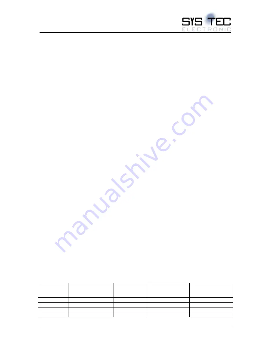
an I2C device has an input capacitance of 8pF. A PCB trace has 0.15pF/mm of trace length. The Table
10 shows the recommendations.
LS1021A
signal name
ECUcore I2C-
interface line name
Module pull-
up
Minimum pull-up
resistor on Carrier
board
Maximum
capacitance on
Carrier board
IIC1_SCL
I2C1_SCL
7.
5kΩ
>1.2
kΩ
<85pF
IIC1_SDA
I2C1_SDA
7.
5kΩ
>1.2
kΩ
<85pF
IIC2_SCL
SDHC_/CD/I2C2_SCL -
>1kΩ
<100pF
IIC2_SDA
SDHC_WP/I2C2_SDA -
>1kΩ
<100pF


