User’s Manual
For Models
SM19202FP, SM19202FP-K
SM96202FP, SM96202FP-K
Fast Poll Modems
Document Number 520-01014-001 Rev. C
Страница 1: ...User s Manual For Models SM19202FP SM19202FP K SM96202FP SM96202FP K Fast Poll Modems Document Number 520 01014 001 Rev C...
Страница 2: ...uide is subject to change without notice and does not represent a commitment on the part of Synxcom Inc Synxcom Inc assumes no responsibility for any inaccuracies that may be contained in this User s...
Страница 3: ...For SM19202FP K only 16 S1 7 2 4 Wire Leased Line Operation 17 S1 8 Transmitter Impedance 17 S1 9 Remote Loopback Enable 18 S1 10 Reserved Test Only 18 S2 1 through S2 3 Transmit Level 18 S2 4 Receiv...
Страница 4: ...RS 485 Device 24 LEDs 26 Loopback Control Switch 26 Appendix A Troubleshooting 28 Problem Solving 28 Appendix B Specifications 29 General Specifications 29 Mechanical Specifications 30 Interface Conn...
Страница 5: ...ll Rack mount Modem Board 14 Figure 2 6 SM19202FP Modem Transmission Line Interface 22 Figure 2 7 Pin Locations on the Modem s RJ 11C Jack 24 Figure 2 8 Loopback Diagnostic Modes 27 Figure 2 9 Back to...
Страница 6: ...compatible with Bell 202 and ITU T V 23 modems The SM19202FP is the most technologically advanced modem on the market Boasting a fast DSP processor and automatic adaptive equalizer the SM19202FP mode...
Страница 7: ...extended temperature range of 40 C to 85 C Designed with coupling transformers for high voltage isolation and common mode noise rejection in industrial and commercial environments Operate over voice...
Страница 8: ...odem Modem Remote Terminal Figure 1 1 Point to Point Network Using the SM19202FP Modem Workstation Modem Modem Modem Modem Modem Modem Remote Terminal Remote Terminal Figure 1 2 Multipoint Polling Net...
Страница 9: ...uctor for stand alone units only A DC power cable model SM19202FP DC modem only This User s Manual or CD ROM If your package contents are damaged or missing contact your place of purchase Additional I...
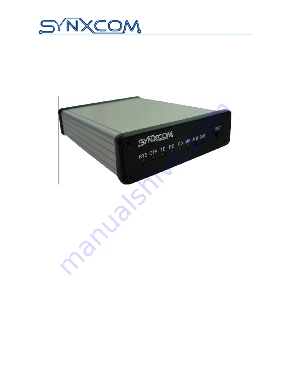
Страница 10: ...e Loopback Control Switch on page 26 Figure 2 1 Front View of the SM19202FP Modem Back View Figure 2 2 shows the back view of the SM19202FP stand alone modem Starting from the left side this view show...
Страница 11: ...ow the steps below to configure the modem s DIP switches to match your DTE RTU interface requirement and the transmission line characteristics If you are not certain about your system s parameters or...
Страница 12: ...s The S2 settings apply for both high speed fast poll QAM and low speed FSK modes 3 After you change the DIP switch settings recycle power to the modem to have the settings take effect NOTE The DIP sw...
Страница 13: ...Installation 13 User s Manual SM19202 Fast Poll Modem Figure 2 4 SM19202 Fast Poll Stand alone Modem Switches...
Страница 14: ...Switches S1 S2 and S3 are miniature switches used to configure all the options and features of the modem Table 2 1 shows the setting of the switches NOTE Switches S1 to S3 are slide switches To config...
Страница 15: ...Range 10 to 43dBm 0 to 30dBm S2 5 TX Cable Equalizer Enabled Disabled S2 6 RX Cable Equalizer Enabled Disabled S2 7 Anti streaming Active Inactive S2 8 RTS CTS Delay Bell 202T only 33 msec 8 msec S2...
Страница 16: ...its character 1 start 1 stop bit 7 data 1 parity E 1 or 8 data with no parity 8 N 1 11 bits character 1 start 1 stop bit 8 data 1 parity 8 E 1 This switch setting is ignored when the modem set at 1200...
Страница 17: ...o RTS option SW1 5 to ON With this option the modem will generate its internal RTS when data is detected from the RTU and turn on the Push To Talk signal to the radio Note Please refer to switch setti...
Страница 18: ...mote digital loopback with another modem Switch S1 9 does not prevent the modem from sending a remote digital loopback request to a remote modem S1 10 Reserved Test Only S1 10 must be OFF for normal m...
Страница 19: ...hen polling on long metallic circuits when the cable exceeds 4 to 5 miles long The cable equalizer is active only when the modem is in QAM fast poll mode 2400 bps or higher S2 7 Anti streaming S2 7 ON...
Страница 20: ...OFF to ON state i e Switched Carrier mode However if the modems are configured in Constant Carrier mode or the RTS is ON continuously by the DIP switches no training pattern will be sent from the tran...
Страница 21: ...d Chassis Ground S3 6 ON The modem chassis ground and signal ground are connected S3 6 OFF The modem chassis ground and signal ground are not connected Configuring the Jumper Blocks For Stand alone Un...
Страница 22: ...r communication to occur the Rx line of one modem must connect to the Tx line of the other modem The modem s Tx Rx pair are non polarized NOTE The modem does not support leased line operation with DC...
Страница 23: ...ection Figure 2 2 on page 10 shows the connection to the Model SM1920FP s power interface shows the connection to the Model SM19202FP DC s power interface WARNING Before you connect a voltage source o...
Страница 24: ...ce The modem rear panel provide an RJ 11C module jack connector for a 4 pin RS 485 or RS 422 interface in the event that your DTE or RTU does not support the RS 232 interface see Figure 2 2 on page 10...
Страница 25: ...nstallation 25 User s Manual SM19202 Fast Poll Modem 2 3 4 5 RxD RxD TxD TxD Modem 4 wire RS 485 Connection RJ 11C DTE RTU 2 3 4 5 RxD TxD RxD TxD Modem 2 wire RS 485 Connection RJ 11C DTE RTU Not Use...
Страница 26: ...32 port of the modem the transmit data is loop back to the DTE as receive data This test will verify the modem transmitter receiver and its RS 232 interface along with the connecting cable Local digit...
Страница 27: ...le in fast poll mode at 2400 bps or higher Figure 2 8 shows these three loopback diagnostics Transmitter Receiver Transmitter Receiver RTU Transmitter Receiver Transmitter Receiver RTU Transmitter Rec...
Страница 28: ...LEDs are off Check the connecting RS 232 or RS 485 cable between the DTE and the modem The MR DSR LED Modem Ready Data Set Ready on the front panel should be ON when the modem is idle Modem does not...
Страница 29: ...s 24 AWG with TX and RX cable equalizer Up to 25 miles for FSK modes Operating modes 2 wire half duplex or 4 wire full duplex over leased or private line Modulation QAM High speed fast poll mode FSK B...
Страница 30: ...module Interface connectors Leased Line 5 position screw terminal includes earth ground Data Terminal Equipment DB 9 female connector for RS 232 RJ 11C modular jack for RS 485 Interface Connector Pin...
Страница 31: ...ta Set Ready Modem Ready RTS Input 7 Request To Send CTS Output 8 Clear To Send RS 485 DTE Interface Table B 3 RS 485 DTE Interface RJ 11 Pin Number Corresponds to Signal Name Modem Input or Output 1...
Страница 32: ...nxcom shall make the final determination as to the existence and cause of any alleged defect No liability is assumed for expendable items such as lamps and fuses No warranty is made with respect to cu...
Страница 33: ...umber tag The serial number for each item you wish to return A description of the problem you are encountering The cause of the problem if known A product support specialist may call to verify that th...
Страница 34: ...RMA Procedure 34 User s Manual SM19202 Fast Poll Modem...