background image

Surgical Technique  USS™ Low Profile Spine System  DePuy Synthes    9

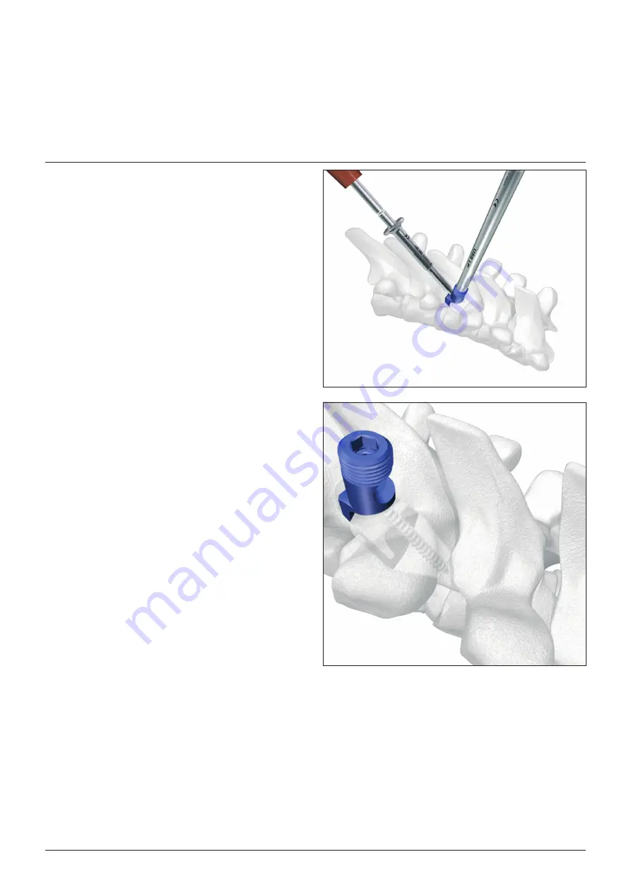
Pedicle Hook Positioning

5. Insert screw Ø 3.2 mm

Select a suitable length USS Screw for Pedicle Hook and 
insert it into the  previously prepared drill hole using the 
hexagonal screwdriver and the holding sleeve.

The pedicle hook is now attached to the pedicle.

Содержание USS Low Profile

Страница 1: ...Thoracolumbar posterior fixation system with side opening screws and hooks USS Low Profile Spine System Surgical Technique...

Страница 2: ...mantling of multi part instruments as well as processing guidelines for implants please contact your local sales representative or refer to http emea depuysynthes com hcp reprocessing care maintenance...

Страница 3: ...tioning 7 Lamina Hook Positioning 10 Angled Lamina Hook Positioning at the Transverse Process 11 Rod Contouring 12 Tightening of Construct 13 Introduction of Rods Into Side Openings 15 Distraction or...

Страница 4: ...and delivery of the Curriculum Stability Alignment Biology Function 1 2 AO Spine Principles Stability Stabilization to achieve a specific therapeutic outcome Alignment Balancing the spine in three dim...

Страница 5: ...e handle 2 Picking up of implants Insert the tip of the Stick into the head of the implant 1 Tighten the Stick to the implant by rotating the knurled knob of the USS Universal Handle 2 Release of Stic...

Страница 6: ...and 7 0 mm screws 388 538 Pedicle probe 2 8 mm length 230 mm for 4 2 mm screws 388 540 Pedicle probe 3 8 mm length 230 mm for 5 0 and 6 0 mm screws 388 539 Pedicle probe 4 8 mm length 230 mm for 7 0 m...

Страница 7: ...pedicle Continue opening the pedicle canal using one of the USS Pedicle Probes Precaution If the probe resists advancement use image intensifier control to check the position and orientation 2 Probe...

Страница 8: ...ropriate pedicle screw from the tray as described on page 3 Insert the screw into the prepared pedicle until the screw head is well seated i e the side opening of the implant head should point in the...

Страница 9: ...le hook Prepare the pedicle using the USS Pedicle Feeler Place the pedicle feeler between the inferior and superior facet joints Precaution Carefully check that the instrument is placed in the articul...

Страница 10: ...positioner and also by pushing laterally The pedicle hook should not move Gently tap the hook positioner with a hammer to firmly seat the hook Remove the hook positioner and the han dle The Stick rem...

Страница 11: ...s 9 Pedicle Hook Positioning 5 Insert screw 3 2 mm Select a suitable length USS Screw for Pedicle Hook and insert it into the previously prepared drill hole using the hexagonal screwdriver and the hol...

Страница 12: ...amina with a bone rongeur Check the seat for the lam ina hook using the USS Lamina Feeler Remove the lamina feeler 2 Position lamina hook Pick up an appropriate lamina hook from the tray with the Stic...

Страница 13: ...the transverse process Remove the lamina feeler Warning Aim for a hook position as medially as possible in order to limit stress on transverse pro cess 2 Position angled lamina hook Pick up an appropr...

Страница 14: ...ng Pliers with Rolls for USS Rods 388 910 USS Bending Irons left right 388 920 Use a trial rod to determine the shape and length of the rod to be inserted Contour the rod using either the bending plie...

Страница 15: ...iversal handle The Sleeve and Nut are picked up with the universal handle from the tray Make sure that the upper side of the Nut is correctly oriented i e the crank of the Nut faces downward and fits...

Страница 16: ...ck with the Socket Wrench with L handle if every sin gle implant is firmly tightened to the rod The coun ter torque instrument is used simultaneously Also check that the rods overlap the screws at the...

Страница 17: ...ping Pliers for USS Implants Using the Rod Introduction Pliers Persuader The Persuader is used in situations when the distance between implant and rod is significant The Persuader permits introduction...

Страница 18: ...located on the side of the Persuader with the arrow pointing to the outer side 1 Pick up a Sleeve from the tray 2 2 Locate Persuader on implants Slide the cylinder of the Persuader over the Stick and...

Страница 19: ...must face upwards The lever must be pulled and then released so that the fork of the support engages in the hexagon of the Stick 4 Bring rod towards side opening of implant Place the spreader forceps...

Страница 20: ...position a either try to align the screw to the rod by slightly turning the Stick using the USS Socket Wrench 6 mm b or gently tap the sleeve pusher to position the Sleeve on the implant using the USS...

Страница 21: ...tip of the instrument is placed on the sleeve of the implants Options Use one of the following alternative methods when for ceps cannot be applied directly to the implants because the neighbouring im...

Страница 22: ...instrument with L handle Rod connectors allow the bridging of lateral distances in cases where the rod is offset from the implant The Rod Connector can be attached to the rod at any point dur ing the...

Страница 23: ...insert the ribbed part of the Rod Connector in the side opening of the implant 1 Tighten the set screw of the Rod Connector using the small hexagonal screwdriver 2 2 Connect Rod Connector to implant...

Страница 24: ...structions for Use for specific information on Intended use Indications Contraindications Warnings and Precautions Potential Adverse Events Undesirable Side Effects and Residual Risks Instructions for...

Страница 25: ...Thieme 2 Aebi M Thalgott JS Webb JK 1998 AO ASIF Principles in Spine Surgery Berlin Springer 3 Modular Stabilization System The Universal Spine System in Aebi M Thalgott JS Webb JK 1998 AO ASIF Princi...

Страница 26: ...ently available in all markets This publication is not intended for distribution in the USA Surgical techniques are available as PDF files at www depuysynthes com ifu DePuy Synthes Spine a division of...

Отзывы: