Synapse D16Mio Скачать руководство пользователя страница 10


Page 10 

1315 Directors Row Suite 107 Fort Wayne, IN 46808  

  (260) 496-9668  

  www.atterotech.com 

3 – Device Operation 

Certain features of the DM16Mio such as channel mutes, output 
level, and front panel lockout are controlled using unIFY Control 
Panel application. This is available from the 

customer portal


section of our website. Details of those features are shown in the 
help documentation for unIFY Control Panel. 
 
Some features  of the device are  operated from the various 
controls on the front panel such as the main display. 


3.1 – Display View Operation 

During power up the display will show the Attero Tech logo. Once 
the device is running, the display will switch to showing a normal 
view. If there are any problems, the display will indicate a POST 
(Power-On  Self-Test) error. If this happens contact Attero Tech 
technical support. 
 
Once up and running, the front panel can show various different 
views and is used to control a number of DM16Mio features. To 
save power, the display will turn itself off after 30 seconds  of 
inactivity. To activate the display again, press either of the knobs 
to activate their buttons or the monitor select button. The Display 
Timeout timer can be adjusted in unIFY Control Panel. 
 

*Note: 

Turning a knob will NOT turn the screen back on. It must 

be a button push.


Navigating the views on the display is achieved using the “Menu 
Nav” knob. Rotating this left or right will step through the various 
views available.  If the front panel lock has been activated  by 
unIFY, the panel lock icon will be shown in the upper right hand 
corner of the display and while the “Menu Nav” knob can still be 
used to rotate the different views no further action can be taken 
on any view. 
 

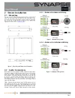
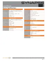
3.1.1 – Bank Metering Views 

 
There are two views for  bank metering. The main part of each 
bank view shows meters for each analog input or output in that 
bank. This view can be used to select the monitor output if the 
panel lock is not active by pressing in the “Menu Nav” button. This 
activates a cursor that can be scrolled used the knob to select one 
of the visible channels. Once the desired channel is selected, 
press the separate “Monitor Select” button and that channel will 
when be routed to the headphone output. 
 

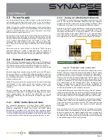
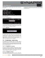
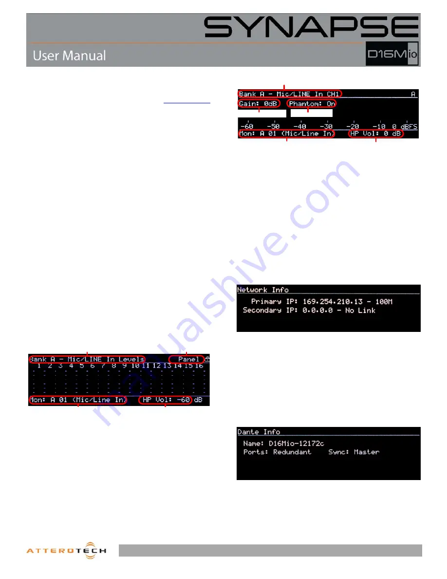
3.1.2 – Channel Metering Views 

 
Each individual input and output channel has its own view. The 
meter itself is shown in the horizontally across the main part of 
the view from left to right. The name of the current channels 
meter being shown is displayed in the upper left hand corner. The 
name in parenthesis that follows the name is the channel name 
that this channels is identified by on the Dante™ network. This 
view can also be used to select the monitor output  if the front 
panel lock is not active. To do so, with the desired channel on 
view, click the “Monitor Select” button. 
 
In the channel metering view, the preamp gain for the channel 
may be configured from the front panel by depressing the Menu 
Nav encoder.  This switches context to the preamp gain control. 
In addition the phantom power state can be toggled by pressing 
the Monitor Select button. To switch context back to the Menu 
Navigation mode. 
 

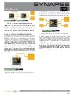
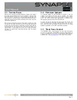
3.1.3 – Network Info View 


The Network info view shows the IP addresses and link speed of 
0the DM16Mio’s interfaces. In redundant mode, both a primary 
and a secondary interface will be shown. The primary port speed 
will always indicate the faster of the two possible primary links if 
they are both used. The same is true the secondary port speed if 
both secondary links are used. 
 
In switched mode, only one interface with its IP address is shown 
and the speed indicated will be the fastest speed of any of the 
four possible links. 
 

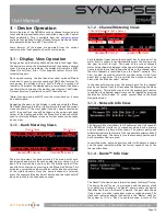
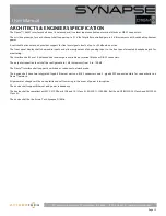
3.1.4 – Dante™ Info View 


The Dante™ info view shows information about the Dante™ setup. 
The device Dante™  name, its port mode and the devices clock 
sync status are all shown. The Dante™ name is name the device 
identifies itself as on the Dante™ network. The port state shows 
if the device is in either redundant mode or switched mode. The 
clock sync indicates whether the device is the “Master” clock for 
the system or if it’s a “Slave” to another device. A state of “No 

Panel Lock

Headphone Volume

Headphone Channel

Screen name

Channel Name (Dante Tx  Name)

Headphone Channel

Headphone Volume

Preamp Gain

P48 Status

Содержание D16Mio

Страница 1: ...Page i 1315 Directors Row Suite 107 Fort Wayne IN 46808 260 496 9668 www atterotech com ...

Страница 2: ...lugs convenience receptacles and the point where they exit from the apparatus 11 Only use attachments accessories specified by Attero Tech 12 Use only with the cart stand tripod bracket or table specified by the manufacturer or sold with the apparatus 13 When a cart is used use caution when moving the cart apparatus combination to avoid injury from tip over 14 Unplug this apparatus during lightnin...

Страница 3: ...OUT OF THE USE OR INABILITY TO USE THIS EQUIPMENT EVEN IF ATTERO TECH LLC HAS BEEN ADVISED OF THE POSSIBILITY OF SUCH DAMAGES IN NO EVENT SHALL THE LIABILITY OF ATTERO TECH LLC EXCEED THE PURCHASE PRICE OF ANY DEFECTIVE EQUIPMENT This warranty gives you specific legal rights You may have additional legal rights which vary from state to state Note This equipment has been tested and found to comply ...

Страница 4: ...ote 8 2 4 2 Using on a Redundant Network 8 2 4 3 Using on Standalone Network 9 3 Device Operation 10 3 1 Display View Operation 10 3 1 1 Bank Metering Views 10 3 1 2 Channel Metering Views 10 3 1 3 Network Info View 10 3 1 4 Dante Info View 10 3 1 5 Version View 11 3 1 6 No Network 11 3 1 7 Identify 11 3 2 Headphone monitoring 11 3 2 1 Headphone Volume 11 3 2 2 Headphone Mute 11 3 3 Factory Reset ...

Страница 5: ...phone amp and a high contrast OLED display to provide quick and detailed feedback for audio confidence monitoring and diagnostics The 24V power supply comes pre mounted to the DM16Mio chassis but there is also support for a secondary external 24V DC supply for optional power redundancy On the network side there is a fully redundant Dante interface utilizing both RJ45 connectors and SFP ports The S...

Страница 6: ...he device is detected by Dante Controller of unIFY Control Panel FRONT PANEL 1 Headphone Jack 2 Headphone Mute Indicator 3 Headphone Volume Mute Knob 4 Factory Reset Switch 5 OLED Display 6 Front Panel Nav Knob 7 Monitor Select Switch 8 Device Power Status LED DEVICE FEATURES REAR PANEL 9 Bank A Inputs 1 16 10 Bank B Outputs 1 16 11 SFP port Primary 12 SFP Secondary 13 Ethernet Port Primary 14 Eth...

Страница 7: ...he analog audio inputs Attach analog audio destinations to the analog audio outputs The analog audio inputs and outputs are balanced so be sure to check what connection type the source and destination devices use in order to connect it correctly Refer to the following diagrams and instructions for connecting different types of audio devices Note Based on the input source type it will be necessary ...

Страница 8: ... configured A Quick Start Guide for AES67 Audio Networking is available from the Attero Tech Customer Portal at https portal atterotech com home v files 560321a2b075c As setup needs may vary by product it may also be necessary to check with the AES67 enabled product manufacturer as well 2 4 2 Using on a Redundant Network The DM16Mio is setup for use in a redundant network out of the box In this mo...

Страница 9: ...etwork Note Connecting either secondary port to a standalone Dante network while the D16Mio is still set in Redundant mode will cause problems due to the IP address setup of the secondary ports having completely different IP addresses Therefore this should be avoided Figure 6 Standalone connection in Redundant mode For full flexibility in a standalone network the DM16Mio should be reconfigured to ...

Страница 10: ...e knob to select one of the visible channels Once the desired channel is selected press the separate Monitor Select button and that channel will when be routed to the headphone output 3 1 2 Channel Metering Views Each individual input and output channel has its own view The meter itself is shown in the horizontally across the main part of the view from left to right The name of the current channel...

Страница 11: ... front panel controls will not operate until the Identify function is disabled 3 2 Headphone monitoring The DM16Mio has a headphone output that can be used to monitor audio signals in the device The currently selected channel for monitoring is shown in the bottom left corner of any of the metering views Selecting a channel can be done from any of the metering views The headphone output has both vo...

Страница 12: ... was active the screen will blank releasing the switch after 5 seconds will then start the factory reset process 3 4 Firmware Updates If a firmware update for the DM16Mio is released it may be applied in the field by the end user or installer The update process takes advantage of the smart firmware update tool in unIFY The unIFY Control Panel application is available from the customer portal on th...

Страница 13: ...nel mounted headphone jack for monitoring The interface shall have 16 balanced line level outputs available on terminal blocks or DB 25 connectors The output attenuation level shall be configurable in 1 dB increments from 0 to 100 dB The Dante interface shall support a switched or redundant network mode The device shall have two integrated Gigabit Ethernet ports on RJ 45 connectors and 2 gigabit S...

Страница 14: ... FCC CFR 47 Parts 15B Class A EN55011 ICES 003 CE EN55022 EN55024 RoHS REACH Environmental Operating Specifications Operating Temperature 0 to 40 C Analog Audio Inputs Input Type 16 Balanced 3 pin line level Terminal Block option 4 TASCAM pinout compatible DB25 balanced analog DB 25 option Input Impedance 10 kΩ Line Mode Maximum Input Levels 24 dBu Pad Active Line Mode 0 005 THD N 0 005 at 3 dBFS ...

Отзывы: